Showing posts with label Tamiya. Show all posts

Sunday, November 11, 2012

How To Read RC Receiver PPM Stream

Many RC Transmitters and Receivers provide access to the PPM Stream, this is a single stream of pulses which includes the information for all of the receiver channels in a single connection. 

This stream can often be accessed by removing the receiver case and adding a single wire to an existing connection within the receiver.

If we can gain access to this stream we can write smaller, faster code and only need a single interrupt pin to read all of the receiver channels.

Using a single built in interrupt to read multiple channels is much faster than using pin change interrupts which leads to a visibly smoother output signal for your servos and ESCs.

This post concludes with a library which can be used to read a PPM stream using a single interrupt. The same library is also able to output upto 18 servo signals from a single Arduino UNO with no additional components. This is an increase of 6 servos over the standard library - its also faster leading to fewer glitches.

Scroll down for a video of the library and an RC Receiver hack in action -

What does the PPM Stream Look Like ?


The stream is made up of a series of short pulses, the first pulse is the start marker. The time between the start marker and the start of the next pulse defines the pulse length for channel one. The time to the next pulse defines the pulse length for channel 2 and so on. The end of the pulse stream is marked by a gap know as the frame space. This gap indicates that there are no more channels to receive and the next pulse will be the start of a new frame. Each frame contains the pulse widths for all of your receiver channels.

Note - unlike servo signals, in a PPM Stream it is the gaps between pulses that defines the pulse width for a channel, not the duration of the pulse itself which can be very short.


How do we find the PPM Stream ?
If your equipment provides direct access to the PPM Stream, skip over this part, if it does not, read on.

The PPM Stream is transmitted between your transmitter and receiver as a single data stream. Inside the receiver this signal is de-multiplexed to produce the individual channels signals as seen in the diagram.


Fortunately for us, the de-multiplexer is most often just a simple shift register clocked by the PPM Stream.


The shift register is clearly visible inside this Hitec HFS-03MM Receiver - its the IC in the center.

The PPM Stream is routed to the clock pin (clock A) of the shift register, the PWM Streams for the individual channels are taken from the shift register outputs (Q1a,Q2a,Q3a).

Usually we would try to read these outputs using three separate interrupt pins, however as they are directly derived from the clock signal we can access the same information by reading the (PPM) clock signal directly. This saves us  two interrupt pins and  a lot of code and memory.

The best bit - read on and theres a ready made library at the end of the post.

Example Datasheet for the 4015 Shift Register used to demultiplex the PPM Signal in the pictured receiver
http://docs-europe.electrocomponents.com/webdocs/05f9/0900766b805f9f8d.pdf

Breaking out the PPM Signal
As above, if your receiver already provides access to the PPM Stream, skip ahead, if not, here are two receivers I have hacked. Its as simple as follows -

To access the PPM Stream from Arduino we need to solder an additional wire to the clock pin of the 4015 shift register.

Example PPM Hack - 1

Hitec 27Mhz FM 3 Channel HFS03MM Receiver - tapping the 4015 shift register to access PPM signal.


Example PPM Hack - 2

Different Receiver, Different Manufacturer, Different Technology - Futaba R152JE 27Mhz AM

The Same 4015 Shift Register inside tapped for PPM Output using thin white wire soldered to the clock pin.


A male jumper wire attached to the hacked Hitec receiver ready for connection to Arduino -


VIDEO - The RC Arduino Library and Receiver Hack in action 


Schematic showing connections in the video above


Multiplexing Servos From Arduino Using PPM Style Signals

In a recent RCArduino Post we showed how a 4017 Decade counter IC could be used to control 10 servos from a single Adruino pin. Each time the counter is clocked by the Arduino it sets one servo output low and sets the next one high. We control the clock pulses to control the pulse widths for the individual servo outputs. Demulitplexing a PPM signal is essentially the same process, the RC Receiver applies a clock pulse to a shift register which shifts the pulse from one output to the next, the longer between clock pulses, the longer the servo pulse.

RC Arduino Serial Servos

Introduction and 10 Servos from 2 Pins
http://rcarduino.blogspot.com/2012/08/arduino-serial-servos.html

20 Servos From 4 Pins
http://rcarduino.blogspot.com/2012/10/arduino-serial-servos-20-servos-4-pins.html

How do we read this RC Receiver PPM Pulse stream with a micro controller ?

Now that we have access to the PPM Stream, how do we read it with our Arduino ?

First of all we need to synchronise with the pulse stream, we do this by waiting for the long pause (the frame space) which indicates the end of one frame and the start of the next.


1) Once we have found this space, we can set our channel counter to 0 and record the current time.

2 ) The next pulse that arrives will indicate the end of the channel 1 pulse. We calculate the channel one pulse width by subtract the time recorded in 1) above from the current time. We also store the current time as the starting point for the channel 2 pulse width

3) We repeat the above process - subtract the last pulse time from the current time to get the pulse width for each of the remaining channels

4) When we have received all of the channels we expect, we start again at 1.

At each stage of the process 1-4 we know whether we are expecting a channel signal or a frame space and so we can use this information to confirm synchronization with the PPM Stream.

Sample Arduino Code For Reading RC Receiver PPM Signal

The following code is taken from the RCArduinoFastLib -

// we could save a few micros by writting this directly in the signal handler rather than using attach interrupt
void CRCArduinoPPMChannels::INT0ISR()
{
  // only ever called for rising edges, so no need to check the pin state
 
  // calculate the interval between this pulse and the last one we received which is recorded in m_unChannelRiseTime
  uint16_t ulInterval = TCNT1 - m_unChannelRiseTime;
 
  // if all of the channels have been received we should be expecting the frame space next, lets check it
  if(m_sCurrentInputChannel == RC_CHANNEL_IN_COUNT)
  {
    // we have received all the channels we wanted, this should be the frame space
    if(ulInterval < MINIMUM_FRAME_SPACE)
    {
     // it was not so we need to resynch
     forceResynch();
    }
    else
    {
      // it was the frame space, next interval will be channel 0
      m_sCurrentInputChannel = 0;
    }
  }
  else
  {
    // if we were expecting a channel, but found a space instead, we need to resynch
    if(ulInterval > MAXIMUM_PULSE_SPACE)
    {
      forceResynch();
    }
    else
    {
     // its a good signal, lets record it and move onto the next channel
     m_unChannelSignalIn[m_sCurrentInputChannel++] = ulInterval;
    }
  }
  // record the current time
  m_unChannelRiseTime = TCNT1; 


Reading the PPM stream with the RCArduinoFastLib

One of the main features of the RCArduinoFastLib is a servo library, why do we need another servo library when the existing servo library is well know, widely used and reliable ?

The standard Arduino Servo library has one major flaw - it resets timer1 at the start of every frame. This means that timer1 cannot be used for timing as easily as you might want. A common approach to overcoming this is to use the micros() function for timing, but this is many times slower than accessing TCNT1 directly.

As our channel input timing and servo output timing is interrupt driven, we really care about speed, every little bit of inefficiency leads to more and bigger interrupt clashes which introduce the ticks and jitter often seen in Arduino based RC projects.

By using the RCArduinoFastServos library we avoid resetting timer1, gain an additional six servos and also the added benefit of being able to user timer1 for very fast timing of our input signals. These lead to a measurable increase in output signal quality with fewer and smaller clashes in short - glitch free projects.

You can find the RCArduinoFastServos library in this post -
http://rcarduino.blogspot.com/2012/11/how-to-read-rc-channels-rcarduinofastlib.html

Sample Sketch - Read PPM Input and Output To Mulitple Servos

A sample sketch you can use to read three channels or PPM is presented below. The sketch can easily be modified to read upto 10 channels.

If you need help or want to ask a question - ask away.

#include <RCArduinoFastLib.h>

 // MultiChannels
//
// rcarduino.blogspot.com
//
// A simple approach for reading three RC Channels using pin change interrupts
//
// See related posts -
// http://rcarduino.blogspot.co.uk/2012/01/how-to-read-rc-receiver-with.html
// http://rcarduino.blogspot.co.uk/2012/03/need-more-interrupts-to-read-more.html
// http://rcarduino.blogspot.co.uk/2012/01/can-i-control-more-than-x-servos-with.html
//
// rcarduino.blogspot.com
//

// Assign your channel out pins
#define THROTTLE_OUT_PIN 8
#define STEERING_OUT_PIN 9
#define AUX_OUT_PIN 10
#define OTHER_OUT_PIN 11

// Assign servo indexes
#define SERVO_THROTTLE 0
#define SERVO_STEERING 1
#define SERVO_AUX 2
#define SERVO_OTHER 3
#define SERVO_FRAME_SPACE 4

volatile uint32_t ulCounter = 0;

void setup()
{
  Serial.begin(115200);

  // attach servo objects, these will generate the correct
  // pulses for driving Electronic speed controllers, servos or other devices
  // designed to interface directly with RC Receivers

  CRCArduinoFastServos::attach(SERVO_THROTTLE,THROTTLE_OUT_PIN);
  CRCArduinoFastServos::attach(SERVO_STEERING,STEERING_OUT_PIN);
  CRCArduinoFastServos::attach(SERVO_AUX,AUX_OUT_PIN);
  CRCArduinoFastServos::attach(SERVO_OTHER,OTHER_OUT_PIN);
 
  // lets set a standard rate of 50 Hz by setting a frame space of 10 * 2000 = 3 Servos + 7 times 2000
  CRCArduinoFastServos::setFrameSpaceA(SERVO_FRAME_SPACE,6*2000);

  CRCArduinoFastServos::begin();
  CRCArduinoPPMChannels::begin();
}

void loop()
{
  // Pass the signals straight through - 

 
  uint16_t unThrottleIn =  CRCArduinoPPMChannels::getChannel(SERVO_THROTTLE);
  if(unThrottleIn)
  {
    CRCArduinoFastServos::writeMicroseconds(SERVO_THROTTLE,unThrottleIn);
  }

  uint16_t unSteeringIn =  CRCArduinoPPMChannels::getChannel(SERVO_STEERING);
  if(unSteeringIn)
  {
    CRCArduinoFastServos::writeMicroseconds(SERVO_STEERING,unSteeringIn);
  }

  uint16_t unAuxIn =  CRCArduinoPPMChannels::getChannel(SERVO_AUX);
  if(unAuxIn)
  {
   CRCArduinoFastServos::writeMicroseconds(SERVO_AUX,unAuxIn);
  }
}


/* DB 04/02/2012 REMOVED The interrupt service routine definition here, it clashes with the attachInterrupt in the cpp file */
/* REMOVE BEGIN 
ISR(INT0_vect) {
 CRCArduinoPPMChannels::INT0ISR();
}

REMOVE END */

Duane B

Friday, October 19, 2012

Lap Timer Build Along Part 4 - Adding the IR Detector

The final part of the lap timer build along is also the easiest part, involving only the IR Detector and an optional LED with current limiting resistors.

The previous steps can be found in the project index section of RC Arduino -
http://rcarduino.blogspot.com/p/project-index.html

A good introduction to IR Detectors is provided on the Ada Fruit website here -

http://learn.adafruit.com/ir-sensor

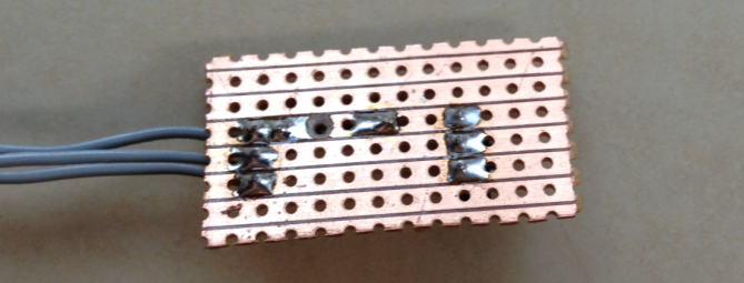
To start our build we need a small section of strip board and a set of three wires for power, ground and IR Out.

These can be soldered to the strip board so each leg of the IR Detector is connected through the copper strips of the strip board to one strand of the cable. In the picture I have used a section of ribbon cable, the cable should be long enough to suite your application, for example long enough to mount the detector on the steering column support of your Kart and allow you to attach the main unit to the steering wheel - don't make the cable longer than necessary it will only get in the way and may pick up interference.

Notice that the IR Detector is facing away from the connecting wires and that there is room for some additional components between the detector and the connecting wires, this is to allow us to add an indicator ID.

Reverse Side View

Next we add a 10K current limiting resistor between the output of the IR Detector and the wire we will be connecting to our Arduino interrupt pin.

For this resistor to have any effect we need to cut the copper track underneath the resistor so that the current has to pass through the resistor, a 3mm or 3.5mm drill bit will do this nicely.

Reverse view showing the cut in the copper track beneath the 10K resistor

Next we need to add the current limiting resistor for our indicator LED, I am using 560, but anything from 500 to 800 Ohms should be fine. This resistor connects from the row with the VCC Pin of the detector to the row below the Vout pin. From here we can also add two short lengths of connecting wire for our indicator LED, on wire should come from the VOut track and another from the track below VOut where we have just added the resistor.

This is to allow use to add an indicator LED which will light whenever the unit receives an IR Signal, this is useful as it will let you know if there is environmental interference such as reflected sunlight or fluorescent lighting.

At this point you should have the following circuit -
You can now add an indicator LED of whatever colour will be most visible in your application. To connect the LED, the long leg should be connected to the length of wire which is soldered to the same row as the 560 Ohm resistor, the shorted leg should be connected to same the same row as the Vout pin of the IR Detector.

You can test this set up immediately by connecting 4 to 6 volts to the circuit, the positive voltage should be applied to the top row, the ground should be connected to the middle row. If you use a TV Remote or the Transponder from part 3 of the build along, you should see the LED Light, if not, try swapping the LED around incase it was soldered in reverse.

This is essentially the same circuit as shown in the Lady Ada tutorial -

http://learn.adafruit.com/ir-sensor/testing-an-ir-sensor

Assuming that you have tested your detector correctly, we can now connect it to the Lap Timer.

To do this we need to connect the Vcc wire (top pin/wire in the picture assuming the detector is facing away from the connecting wires) to the 5V supply of the Arduino. Next we need to connect the center wire to the ground of the Arduino. Finally connect the bottom wire to digital pin 2 of your Arduino.

Congratulations, you have now finished the electronics however to be able to use the lap timer you need to build a small enclosure for the detector, without this sunlight and many type of indoor lighting will saturate your detector so that it is unable to detect signals. As I am based in Dubai where the sun is always fierce I have gone as far as spraying the inside of my enclosure with ultra matt camouflage paint. You can see the enclosures I have used in the following clips of the timer in action, not that the indicator LED is on the outside of the enclosure where we can see it - you knew that already right ?

Build Along Lap Timer in action complete with IR Detector as built in this post


I have recently added a few extensions to the project including a count down mode and support for external audio, you can see the new menu options and see them in action at the track in the following two clips -


New Menu Options
At the track with external audio enabled


The external audio option uses an LM386 based amplifier to drive external speakers. You can use this IC to add big sound to any Arduino project, here is a link to the circuit as used in the Lap Timer -

http://rcarduino.blogspot.com/2012/08/adding-audio-to-arduino-projects.html

If you would like the latest code, contact me through the arduino forum for a zip file containing the full project.

Future Developments - I am considering adding support for three additional transponder types -

1) Magnetic - I am told that many Kart Tracks use a magnetic strip under the track which lapping Karts detect using a window sensor such as you would use for home security.
2) Commercial Beacons - The commercial beacons used at many auto racing tracks use a well know pattern of pulses, it would make sense to support this pattern allowing users to 'arrive and drive' without having to place your own transponder around the track.
3) User selected pulse length - Allow the user to choose a pulse length, this would allow two or three systems to be used alongside each other. All of the calculations needed to build your own unique transponder are linked in previous parts of build along.

Stay tuned.

Duane B
Friday, March 9, 2012

Tyre Testing - 3Racing M-Chassis Tyres

Today was the worst possible day for tyre testing -

Every now and then, the wind turns to blow in from the desert and remind the population of Dubai of the cities desert origin.The best sand storms are brief, 15 minutes of darkness and mayhem as the wind drives a mile high wall of sand across the city.

Today was not like that. Today began with a haze and a wind strong enough to push furniture around the garden. Hours have passed and still no great wall of sand has crashed across the city, but everywhere, inside and outside is covered by a growing film of dust.


Not the best day for tyre testing -


3Racing M-Chassis Tyres

 
I keep A rally car for days like today, it's an M03 with M05 ra uprights, a sport tuned motor and a NICAD battery. The 7.2 volt battery can make the car feel  slow after running my on road LIPO powered cars. As a quick fix I have been waiting for the rally block tyres to wear out so that I can replace them with a set of larger m-grips for a higher top speed.

When I first saw the 3racing tyres, they looked very big. Comparing them with other m-chassis tyres, they are the largest I have seen and so they went straight onto a spare set of rims and the rally car.

Straight on ?

Not really, at over 60 revolutions per second we have to glue our tyres on to keep them on.


Tyre gluing 101
 
1) Wash Everything.

Superglue is incredible stuff, but it won't stick to oil or grease. A lot of RC parts including tyres and the rims are created using molds. In order to be able to remove parts from the mold it is coated with a non stick release agent, if we don't wash this off our parts, paint and glue will struggle to hold.

2) Use The Right Glue

Most glue sold as superglue is a variation of cyanoacrylate, the different variations can work for or against you. If you are gluing tyres with a gap or wedge between the tyre and rim, you can use a thin formula which will run into and around the gap. Thin formulas tend to be fast setting, so if you have a tyre and rim combination that mate without a gap you might be better using a gel formula which gives you time to manually spread the glue between tyre and rim and readjust the fit during the longer set time. 

The 3Racing tyres mate to the rims without a gap and so I used a gel formula.

3) Use A Rubberised Superglue If You Can

If you can find a rubberised formula use it. One of the weaknesses of standard formulas is an inability to flex and withstand shocks. The rubberised formulas are a step towards overcoming this and should perform better in most RC applications.

 
Testing
Testing the tyres was great fun, one of the corners on my test track exits along a wall where a drift of accumulated dust had settled. Coming out of the corner and getting onto the throttle early would get the car power sliding through the dust.


Braking was impossible, the car would take upto 10 meters to stop with every speck of dust working as a ball bearing between the tyres and brickwork. Acceleration was reasonable enough, my guess is that the car scrubs the road clean of dust as it claws its way forward.


Tyre Sizes
The 3Racing tyres have a very square edge to them, this gives them the impression of being much larger than other M-Chassis tyres however having measured them they are only 1mm larger in diameter than the popular Tamiya M-Grip tyres.


Tyre                            Diameter                     Circumference                                 %
3Racing 60 188.57 109
M-Grip 59 185.43 107
Tamiya Rally Block 55 172.86 100
Slicks (Spice etc) 55 172.86 100


This small difference has a big effect on the distance travelled due to the multiplying factor of pi. The table above shows the diameter and circumference of some popular m-chassis tyres. Taking racing slicks as the standard, the 3-Racing tyres travel  9% further per revolution, while this is a huge advantage in the straights, it can easily be lost in corner grip and especially braking.


So are the tyres any good ? its impossible to say based on todays testing, but the ultimate test of any tyre is in the lap time. As soon as the sand clears I will be out with the personal lap timer for an M-Grip, Rally Block and 3Racing show down.

Friday, December 30, 2011

Traction Control Part 1.2 - Taking Control

So far I have used two pairs of IR Emitter, Detector diodes to monitor the speed of the front wheels, I use this information to detect wheel spin based on the assumption that if one of the wheels is spinning more than 20% faster than the other then I have lost traction in that wheel. This is all covered in the post Traction Control Part 1.1.

The next step is to interface the Arduino between the remote control receiver that receives the signal from the users radio and the electronic speed controller that delivers power to the electric motor based on the users signal.

As the first step towards this I will implement a 'Child Mode' for my cars. The idea here is that if I hold the brake for 10 Seconds, the Arduino will enter 'child mode' and map the throttle input range to a more limited 'child' range. This way whenever my son or daughter want to have a go I can discretely hold the brake to activate child mode before passing them the transmitter, a similar signal will be used to revert to standard operation.

Prototype using Arduino to read input pulse width, then use the Servo library to generate output pulse of same width. The picture shows a servo connected rather than the electronic speed control but the pulse, logic and connectivity is the same for both. I prefer testing with a cheap servo rather than a racing motor spinning at 21,000 RPM !


I have had an early version of this working where the Arduino was capturing the throttle pulse width through an interrupt and then using the writeMicroseconds function of the Servo library to control the servo. This proved the concept of decoupling the servo from the receiver and giving the Arduino responsibility for mapping from the input signal to the servo.

During the testing of this code I found that I had a massive electrical noise problem when the Arduino was powered from the same LIPO battery as the rest of the car, this put the project on hold while I investigated strategies for dealing with the noise. I now have the noise under control and in the next few days hope to be able to post the 'Child Mode' code and confirm that the noise really is under control and the strategy used to control it.

Tuesday, December 27, 2011

Anti-yaw control Part 1

I gave a new kit its first run today, its a Tamiya Sand Scorcher which is a reissue of a 30 year old design. It looks fantastic in motion but could really use some on board electronic help to stay on track.


A little bit of history

Back when the kit was issued it would have been powered by a 7.2 volt Nicad battery which took about 18 hours to trickle charge and lasted about 7 minutes. Today I am running the reissue on an 8.4 Volt Lipo which takes an hour to charge and lasts about 30 minutes, its also about half the weight of the original batteries.

The kit itself is very different from todays plastic and carbon kits which contain very few metal parts, the sand scorcher is almost entirely metal with parts made from stainless steel, aluminium and brass. 

Its a real novelty to put together if your used to todays kits, it also makes for a more 'scale' drive as the weightier metal parts cause the car flop, lurch and bounce around far more realistically than a modern lightweight plastic kit.


I am not sure whether its the lighter, more powerful modern day battery, the rear wheel drive chassis, the desert sand or just my driving but the car is impossible to drive in a straight line. Every rear wheel drive radio controlled car I have ever driven has had this problem, but this one is the worst of the lot. One solution which many people have tried with RWD RC Cars is to put a gyroscope into the car.

A gyroscope fitted in my Tamiya M04 Rear Wheel Drive On Road Chassis.


The gyroscope senses the car beginning to fishtail and instantly steers into the skid (counter steers) to keep the car moving forward. This can also be useful over rough ground and jumps where the gyroscope will keep the front wheels pointing into the landing even if the car starts to rotate to the side in the air, this reduces the stress on landing minimising parts wear and breakage, it also keeps the speed up as the car 'digs in' less on the landing.

My F103GT RWD On Road Chassis demonstrating how to 'steer into' a skid or fishtail.

If the rear of the car is skidding left the steering is turned to the left, this is known as 'steering into the skid', this stops the car from spinning out and should allow the driver to straighten out of the skid as the rear regains grip If the car skids to the right we steer to the right, in both examples you can see how the front wheels point straight ahead as a result of 'steering into the skid' its the fact that the front wheels point in the direction of travel that should stop the car from spinning out and allow the driver to regain control.


I have had limited success using gyros, the problem is that the gyroscope is passive, it applies the same level of counter steer regardless of the cars speed and the drivers intentions, for example if I am trying to turn left, the gryoscope will sense the car rotating and tell the wheels to turn right to keep the chassis straight. This counter steering effect is adjustable through 'Gain' this is a static setting which controls how hard the gryo will try to keep the car straight. What we need for effective 'Anti Yaw or Yaw Control' is active gain that keeps out of the way when you want to turn and gets straight on the job when you don't. This is where Arduino comes in.

Project Goals - 

1) Easy to access user interface to set the base level of gain
2) Allow adjustment of the base level without needing to restart the Arduino or the Gyroscope
3) Actively adjust gain around the base level based on the signal coming from the controller
3.1) If the controller is telling the car to turn, reduce the gain so that the gyro does not fight the turn
3.2) If the controller is telling the car to accelerate or brake, increase the gain to prevent fishtail and spinout
4) Provide a simple means of turning the active components off for easy comparison between 'active anti yaw', 'passive gryo based anti yaw' and no anti yaw.
5) Provide an easy interface to set a maximum and minimum range for the servo, these limits will prevent the software/user command combination from sending signals to the servo which would cause it to exceed the mechanical limits of the model.
5.1) Record the range limits to the EEPROM for persistent storage
6) Record any operating errors to the EEPROM for persistent storage and retrieval
7) Use the project as a test bed for decoupling noise before progressing the traction control project


More soon. In the meantime, here is another picture of my fresh 'weathered' Sand Scorcher, the bodyshell is white plastic which I have painted and otherwise abused to look like 30 year old metal.


Monday, December 26, 2011

Spice Vs M-Grips


M-Grips (blue) for the win in this case. I would have expected the Spice tyres to show the highest G's but it was early morning so the spice would be struggling to get up to temperature.

Sunday, December 25, 2011

Data Logging Part 3 - Data Logged !!!

I have finally logged some data to the SD Card. To make life super easy I am logging the data is CSV format, this is a very simple text based format that can be imported by any spreadsheet application, in my case I am using Excel. The charts are simply generated by selecting the data and clicking the Excel chart icon.

The first test - Figure of 8 and Max Acceleration, Max Braking.

This first chart plots the X,Y,Z Axis as red, orange, pink. I would not have expected to see much movement in the Z axis as the car is running on reasonably flat tarmac however I am running smaller tyres than normal and so the car is dragging on the road where I haven't yet raised the suspension to compensate. Bumping along small stones is one possible cause for the movement in the Z Axis. For the remaining charts I have removed the Z - Axis so that we can see whats happening in the X and Y Axis (lateral G-Force and acceleration/braking).


I am quite pleased with the data here. For the first half of the test I was driving in a steady figure of 8, you can see this in the graph where on the left side the pink (acceleration/braking) line is steady and the lateral G-Forces swing from positive to negative as the car corners to the left and then to the right.

For the second half of the test I changed to accelerating and braking, again this shows up clearly as the pink line now moves from the positive to the negative, accelerating to braking. Interestingly you can see that the M03 is able to brake much harder that it can accelerate - pretty much what you would expect but its nice to see it captured consistently. I can also see from the red line that at the end of my acceleration and braking runs I always turned to the right to start the next run. The final point of interest is that the test strip was on a slope, and you can see this in the acceleration and braking runs where the peak G-Force under braking is higher on the first and third runs (uphill) than on the second and fourth runs (downhill).


Scatter Graph
This last graph plots each data point on an X and Y Axis, with more data it should provide a reasonable representation of the traction circle.

Again you can see that I spent more time turning left and that the brake force was about 50% higher than the acceleration.
Thats the easy bit finished. Now I need to develop a test protocol to confirm the quality of the test data. I also need to run some tests comparing spinout data with controlled high speed cornering, its pretty useless data if spinouts can't be determined from successfully negotiated high speed corners.

Thursday, December 22, 2011

Data Logging Part 2 - A User Interface

My first attempt at a micro controller user interface -
I am pretty happy with it, its a thousand times better than the horrible interfaces you get on your average Electronic Speed Controller. Take the example of a Tamiya TEU104BK, the user interface consists of a single 1*2 mm grey button hidden in a 4mm recess in the case. The button and indicator light are in highlighted area in the pic below, a 10mm push button is included for size comparison.


While I have used a great big bright red 10mm push button, I haven't completely broken away from tradition, the interface still relies on the users ability to count and interpret a sequence of flashing lights. The reason for this is that mirco controllers provide a limited number of inputs and outputs. Each of these inputs/outputs can be extremely powerful so using them up with indicators, displays and multiple push buttons is an unacceptable waste of resources.

The data logger user interface


1 Big Red 10mm Push Button
1 Bright Red LED to signal 'Recording'
1 Bright Green LED to signal 'Sending recorded data over the serial interface'

The system has 5 states -

StateMeaningRecord IndicatorSerial Indicator
IdleNot currently doing anythingBrief flash every 2 secondsAs Record
RecordRecording Data to SD CardOnOff
SerialReading SD Data and writing to serialOffOn
Memory FullNo more data can be recordedOn 1 Second/Off 1 SecondAs Record
ErrorSomething is wrongRapid Alternate with SerialRapid Alternate with Record


To move between states the push button must be held for 1 second or more. To enter record from idle 1 Second, to enter Serial from idle 4 Seconds, to exit either record or idle 1 second.

All I need now is a Micro SD Card and the data logger is up and running.

Monday, December 19, 2011

Data Logging Part 1 - Acceleration

Its so easy to build circuits and programs with the Arduino that I have a few projects progressing side by side on the same hardware. In this project I intent to record performance data on board my RC Racer then upload the data for analysis on the PC. Something which I see as very simple but very useful is the ability to record and visualise the traction circle for different setups. For my purposes the traction circle will be plotted from the X and Y G-forces acting on my car, to sense and record these forces I am using an ADXL335 3-Axis Accelerometer and a Micro SD Card. Both of these are available on easy to use 'breakout' boards that can be plugged directly into the Arduino UNO.
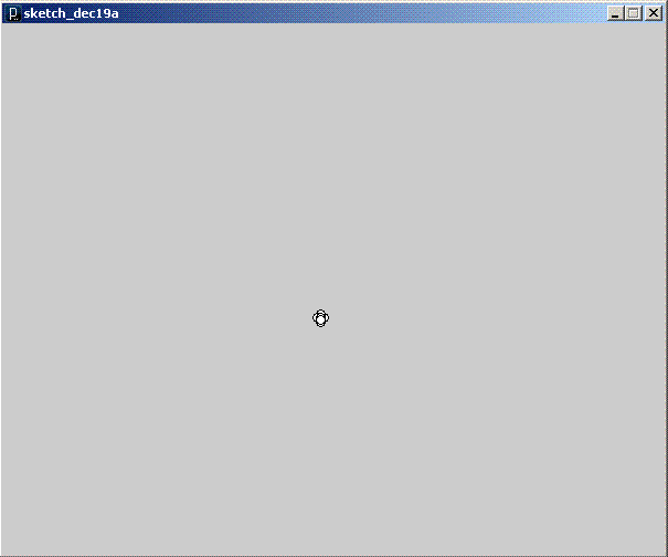
The two plots above are produced from live data coming from the Arduino into my PC, I am using 'Processing' to display the results. The screen area represents +-1G in the X and Y Axis, Z is not plotted. The first plot is generated with the board flat on the table. The second plot is the result of me tapping the side of the table to generate some movement in the X-Axis, then tapping the front of the table to get some action on the Y-Axis, but the really interesting plot is the next one -

Here I have used the constant 1G acceleration provided by good old fashioned gravity. By tilting the board from one side to the other I can use gravity to apply 1G of acceleration to the left and then the right. You can see the result of this in the lines running right, up and down from the center. The diagonal line running from the center to the top right is the result of me trying to 'draw' the line by progressivley tilting the board and letting gravity do the work. This was surprisingly difficult, it had that addictive quality that the simplest of games have - something thats quick and easy to understand, takes a while to master and can always be improved upon. I can think up a dozen gaming applications for this - for example physical tetris where you actually have to rotate the controller to rotate the tiles and then swing the control to the left or right to position tiles. Another application would be target based sports simulations, the sensor is sensitive enough to pick up hand tremors.

Getting back to the main purpose of this project, the left side of the screen shows a sample of a traction circle I have generated by rotating the board which is sensing the constant 1G force of gravity over a range of angles. In practice most of the plot points would be toward the center of the screen but this provides a quick bench test and proof of concept. The sensor I am using can sense up to 3G, and also records the z-axis which I am recording but not currently plotting. I have no idea what to expect in the car, probably less than 1G but will get some plots up with different tyres in the next day or so - I know that racing tyres are worth every penny compared to stock tyres and soon I will be able to prove it !

Sunday, December 18, 2011

Traction Control Part 1.1 - Monitoring Wheel Speed

The Atmega328 microprocessor at the heart of the Arduino is able to process 16 million operations per second.

The wheels or my test car running at full speed turn 68 times per second.

The Arduino is able to perform around a quarter of a million operations in the time it takes for my radio controller car wheel to rotate once.

Given these numbers I was confident of being able to monitor the speed of all four wheels, however I wasn't so sure of how to electronically sense the mechanical movement of the wheels. There are several challenges here -

1) I can't add anything to the wheel which upsets the balance, so no metal or magnets.
2) I have very little room to work with between the wheel and the wheel hub so have no option to add beam breakers to the wheel.
3) The front wheels need to turn freely in order to steer so I cannot impede their movement and cannot rely on a constant angle between the wheel and the sensor.

The solution I chose was to use pairs of infrared emitter and detector diodes.

  • Cheap
  • Easily Available
  • Non-invasive
  • Side facing design

The 'side facing design' means that the light is emitted and detected through the side of the diode, in our case this is an advantage as the diodes are very slim in profile and as the leads exit at the bottom this allows us to mount the diodes lying flat. The diodes are 2mm tall when mounted this way leaving around 10mm between the wheel hub and the wheel.

Most IR Sensor circuits rely on 'beam breaking' where an object passes between the emitter and the detector - breaking the beam. This is not an option in my case due to the small amount of space available and the amount of vibration present in the wheel and the hub.

One idea I had was to try sensing reflectance instead, to do this I initially set up a circuit with both the IR Emitter and Detector facing out from a prototype board. I then fixed a small strip of white tape to one of my tyres. At low speeds I was able to detect the white tape passing the in front of the sensors and count the revolutions per second. At this stage I was not concerned about higher speeds as the design was far from optimal.

The next step was to develop a package for the IR pair that could be mounted in the car between the wheel and the steering hub.


To do this I first trimmed the leads of the diodes and soldered on some flexible wire which I could later route around the car. I also used a layer of heat shrink to protect the wire joint from electrical shorts and mechanical wear.

Next I used double sided tape to mount the diodes to a square of styrene which I then glued to the wheel hub.


You should be able to spot the sensor mounted to the steering hub in the center of the picture below.


To ensure the best quality data I needed a sharp transition from reflecting to non-reflecting. To achieve this I sprayed the inside of the wheel satin black and then mounted a strip of 'bare metal foil'. This is an aluminum foil that has an adhesive on one side, its usually used for adding metal details to small 1/32 and 1/43 model cars and for this reason is exceptionally thin and therefore light enough not to upset the balance of the wheel.


On the other end of the sensor wires I soldered individual header pins allowing me to easily plug the sensors into my prototyping board.


Note that as I used a common ground wire for the two LEDs reducing my connetions from four to three.

I have made and mounted a set of sensors for both front wheels and now that I have proved the concept will eventually make sets for the rear wheels in order to monitor traction at all four corners.


Next up - connecting to the Arduino and writing the software, here is a preview -

Tuesday, December 6, 2011

What can I do with an RC Car and Arduino ?

One of the strengths of the Arduino is the ease with which it can be interfaced with inputs (sensors) and outputs (motors, servos, LEDs, speakers etc, etc, etc)

In the coming weeks I hope to be able to build the following radio controlled car based projects

1) G-Force Logging - use an accelerometer connected to the Arduino to measure acceleration and deceleration and log this data to an SD Card.

2) Traction Alarm - use infra red sensors to measure the speed of the wheels and sound an alarm or flash a visual signal whenever the speed of one wheel exceeds the other by a given percentage

3) Training Mode - It would be nice to have a button to push to put a car in training mode, this would limit the power to 25 or 50% allowing me to pass the controls to my kids and then easily return the car to full power when I get the controls back

4) Traction Control - This is really a combination of 2 and 3 with a lot of extra work required. The circuit from 2 would be used to detect wheelspin and the circuit from 3 would be used to manage the power being requested from the motor. With some experimentation it should be possible to create a program to vary the motor power based on the degree of wheelspin detected and the amount of power being requested by the driver. It would also be nice to combine this with 1) to be able to log acceleration with and without traction control.

5) Traction Contol with Brake Force Control - Assuming that 4) can be made to work, the next logical step is to add active brake by using the same principle to detect a wheel locking and automatically reduce the brake force.

6) Yaw control - Yaw is movement in the left to right axis, like the fishtailing that rear wheel drive cars produce under hard acceleration. It is possible to sense this using a gyroscope and have the car automatically correct by steering into the skid.

7) Active Torque Distribution - In a twin motor car it should be possible to send power to which ever axle is generating the most grip

And now a quick look at some cars

Rear Wheel Drive Tamiya F103 GT with HPI Zonda Bodyshell


Front Wheel Drive Tamiya M03 with Kamtec Beetle Bodyshell


This final car is a front wheel drive car joined to a rear wheel drive car, it was an interesting project and very fast, much faster than the two donor cars.

Custom 4WD Twin Motored Car

Unfortunatley as fast as this car was, the handling was too unpredictable. The rear of the car was built from a Tamiya M04 a car with notoriously bad handling. Getting this car to handle will require Active Torque Distribution at the very least.


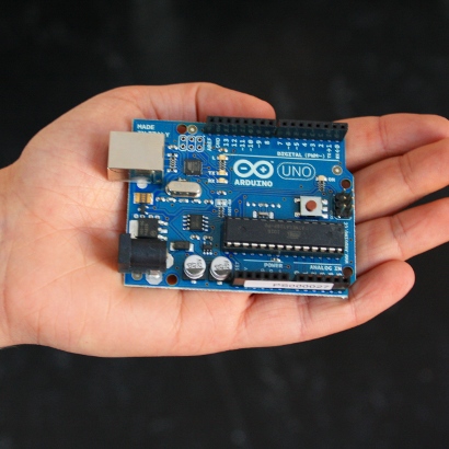
What is an Arduino ?

What is an Arduino ?

If you have ever wanted a small gadget to control something with, Arduino is the answer.

The Arduino team have taken a microcontroller which is basically a single chip computer and built an easy to use physical computing platform around it.

You already have countless microcontrollers in your life, there is one in your washing machine for instance. On thier own microcontrollers can be very difficult to use, difficult enough to be beyond the access of all but the most dedicated hobbyists. What the Arduino team have done is produce a design which reduces the learning curve to the absolute minimum while still providing a powerful platform for project development.


What is most impressive about the arduino is the range of sensors available, my own interest is in measuring the effect of setup changes on my radio controlled cars and also in providing active in car control. There are off the shelf boards and software that literally allow the sensors I need to be plugged in to the Arduino with no need to seperatley source individual electronic components or even get deep into understanding thier purpose.


Its a bit like building a PC, if I need a graphics card, I buy a graphics card, I don't need to buy 300 components or even understand what they do, I just buy and plugin a ready made solution which does what I want.

Arduino does what I want.