Showing posts with label Amplifier. Show all posts

Friday, October 19, 2012

Lap Timer Build Along Part 4 - Adding the IR Detector

The final part of the lap timer build along is also the easiest part, involving only the IR Detector and an optional LED with current limiting resistors.

The previous steps can be found in the project index section of RC Arduino -
http://rcarduino.blogspot.com/p/project-index.html

A good introduction to IR Detectors is provided on the Ada Fruit website here -

http://learn.adafruit.com/ir-sensor

To start our build we need a small section of strip board and a set of three wires for power, ground and IR Out.

These can be soldered to the strip board so each leg of the IR Detector is connected through the copper strips of the strip board to one strand of the cable. In the picture I have used a section of ribbon cable, the cable should be long enough to suite your application, for example long enough to mount the detector on the steering column support of your Kart and allow you to attach the main unit to the steering wheel - don't make the cable longer than necessary it will only get in the way and may pick up interference.

Notice that the IR Detector is facing away from the connecting wires and that there is room for some additional components between the detector and the connecting wires, this is to allow us to add an indicator ID.
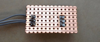
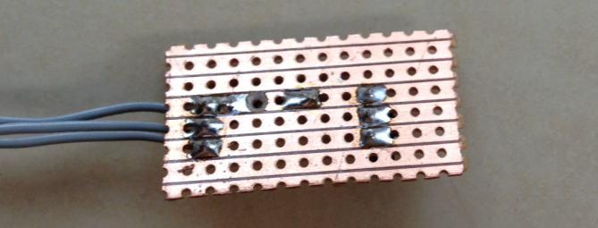
Reverse Side View

Next we add a 10K current limiting resistor between the output of the IR Detector and the wire we will be connecting to our Arduino interrupt pin.

For this resistor to have any effect we need to cut the copper track underneath the resistor so that the current has to pass through the resistor, a 3mm or 3.5mm drill bit will do this nicely.
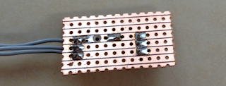
Reverse view showing the cut in the copper track beneath the 10K resistor

Next we need to add the current limiting resistor for our indicator LED, I am using 560, but anything from 500 to 800 Ohms should be fine. This resistor connects from the row with the VCC Pin of the detector to the row below the Vout pin. From here we can also add two short lengths of connecting wire for our indicator LED, on wire should come from the VOut track and another from the track below VOut where we have just added the resistor.

This is to allow use to add an indicator LED which will light whenever the unit receives an IR Signal, this is useful as it will let you know if there is environmental interference such as reflected sunlight or fluorescent lighting.

At this point you should have the following circuit -
You can now add an indicator LED of whatever colour will be most visible in your application. To connect the LED, the long leg should be connected to the length of wire which is soldered to the same row as the 560 Ohm resistor, the shorted leg should be connected to same the same row as the Vout pin of the IR Detector.

You can test this set up immediately by connecting 4 to 6 volts to the circuit, the positive voltage should be applied to the top row, the ground should be connected to the middle row. If you use a TV Remote or the Transponder from part 3 of the build along, you should see the LED Light, if not, try swapping the LED around incase it was soldered in reverse.

This is essentially the same circuit as shown in the Lady Ada tutorial -

http://learn.adafruit.com/ir-sensor/testing-an-ir-sensor

Assuming that you have tested your detector correctly, we can now connect it to the Lap Timer.

To do this we need to connect the Vcc wire (top pin/wire in the picture assuming the detector is facing away from the connecting wires) to the 5V supply of the Arduino. Next we need to connect the center wire to the ground of the Arduino. Finally connect the bottom wire to digital pin 2 of your Arduino.

Congratulations, you have now finished the electronics however to be able to use the lap timer you need to build a small enclosure for the detector, without this sunlight and many type of indoor lighting will saturate your detector so that it is unable to detect signals. As I am based in Dubai where the sun is always fierce I have gone as far as spraying the inside of my enclosure with ultra matt camouflage paint. You can see the enclosures I have used in the following clips of the timer in action, not that the indicator LED is on the outside of the enclosure where we can see it - you knew that already right ?

Build Along Lap Timer in action complete with IR Detector as built in this post


I have recently added a few extensions to the project including a count down mode and support for external audio, you can see the new menu options and see them in action at the track in the following two clips -


New Menu Options
At the track with external audio enabled


The external audio option uses an LM386 based amplifier to drive external speakers. You can use this IC to add big sound to any Arduino project, here is a link to the circuit as used in the Lap Timer -

http://rcarduino.blogspot.com/2012/08/adding-audio-to-arduino-projects.html

If you would like the latest code, contact me through the arduino forum for a zip file containing the full project.

Future Developments - I am considering adding support for three additional transponder types -

1) Magnetic - I am told that many Kart Tracks use a magnetic strip under the track which lapping Karts detect using a window sensor such as you would use for home security.
2) Commercial Beacons - The commercial beacons used at many auto racing tracks use a well know pattern of pulses, it would make sense to support this pattern allowing users to 'arrive and drive' without having to place your own transponder around the track.
3) User selected pulse length - Allow the user to choose a pulse length, this would allow two or three systems to be used alongside each other. All of the calculations needed to build your own unique transponder are linked in previous parts of build along.

Stay tuned.

Duane B

Wednesday, September 19, 2012

Lap Timer Build Along Part 3 - Timer Based Transponder

This post continues the RCArduino Lap Timer Build Along Series.

Previous steps can be found here -

Initial build along and videos -
http://rcarduino.blogspot.com/2012/07/lap-timer-build-along-part-one.html

Introduction to the timer based transponder and the required parts list -
http://rcarduino.blogspot.com/2012/08/lap-timer-build-along-part-2-transponder.html

Here are two quick demos of the system in action at the Pro RC Track in Dubai, the first shows the bread board build along lap timer and an enclosed stripboard version. The second video shows external audio enabled for lap time countdowns and fastest lap/not fastest lap indicator tones.


Transponder Overview
The transponder works by generating a simple infrared signal very similar to the one your TV Remote generates. This is an established technique which is widely used at RC Tracks, kart tracks and even automobile race tracks. If your track has an existing IR Transponder you can use the existing signal and do not need to build your own transponder. Part 4 will show you how to do this.


If you plan to build your own transponder read on.

The transponder can be powered in one of two ways -

1) Using dedicated power - If you are using the transponder in an automobile or kart, you can use a 9 Volt battery or 4 AA batteries to power the circuit directly.

2) Using buffered/shared power - The 555 Timer is a notoriously noisy component, if you intent to share power with any sensitive equipment such as an RC Receiver, you will need to buffer the shared power from the 555 timer. A cheap and effective solution is to use a 7805 voltage regulator, the final stages of this post show how to add this component.

RC Car Power
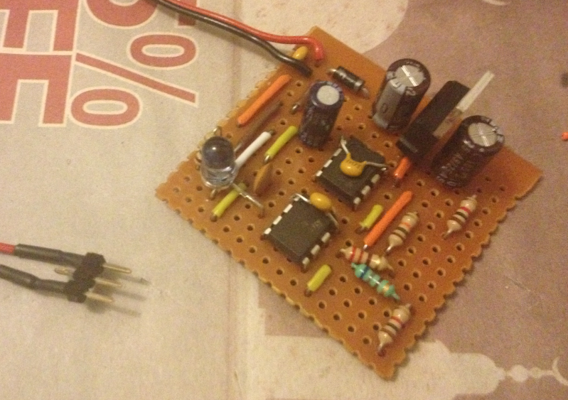
The transponder design has been extensively tested in many cars at the ProRC Track in Dubai. The transponder can easily be connected to the balance plug of a LIPO battery using a 3 pin section of PCB Header or a male balance plug if you have one. When sharing power in this way it is important to use the 7805 regulator circuit to prevent interference with the models RC Systems.

One of the test cars - The current m-chassis lap record holder at the Pro RC Track - lots of carbon, anodized aluminium and threaded oil shocks all around.

 
If you are not using shared power you will not need to complete the final few steps of the build (stop at step10) however if you expect to share power with any sensitive equipment at some point in the future it is worth including these steps.

How does the transponder work ?

The transponder uses the same technique and components as your TV Remote - an Infra Red light emitting diode is switched on and off 38,000 times per second, this is our carrier frequency. The carrier is generated by one of the 555 timers however in order to transmit a signal or data we need to alter the carrier in some way. The transponder uses a very simple signal - a pulse of 500 microseconds, this is generated by the second timer which simply switches the first timer on and off.

In the final part of the build series we will add the IR Detector to our Arduino circuit, the IR Detector is tuned to the 38Khz signal of the transponder. Remember we are using two timers ? One to generate the 38Khz signal and another to pulse it at 1Khz ? This provides a very simple encoding which allows us to look for pulses 500us long and know that we are receiving transponder signals rather than reflected sunlight, TV Remote signals or signals from other track side transponders.


Some Alternative Transponders

The job of the transponder is to 1) Switch the diode on and off at a frequency of 38,000 times a second. 2) To enable and disable 1) At a frequency of 1,000 times a second. 

In order to do this we use two connected 555 timers, the first generates the 38Khz signal and the second one enables and disables this signal at the much lower frequency of 1Khz. 

The transponder circuit can be replaced with any simple circuit capable of generating two fixed frequency square waves. 

Options include microcontrollers, NAND oscillators, op-amp oscillators - anything that can generate a squarewave.


Building The 555 Timer Transponder - Before and After
The transponder can be built on a piece of strip board 16 holes wide by 14 deep. To make sure that this is the final size of you board, remember that the rows and columns you cut will be unusable, you need 16*14 inside the cut area.

The copper strips should be running from left to right across your board - this is the orientation used throughout the build.
The Schematic
The circuit is reasonably simple with only 11 components required for pit wall use and an additional four if you plan to use the circuit in an RC vehicle.

Due to the angle in some of the pictures, its useful to double check your component placement against the schematic, also have a look at pictures from later stages for a cross reference.
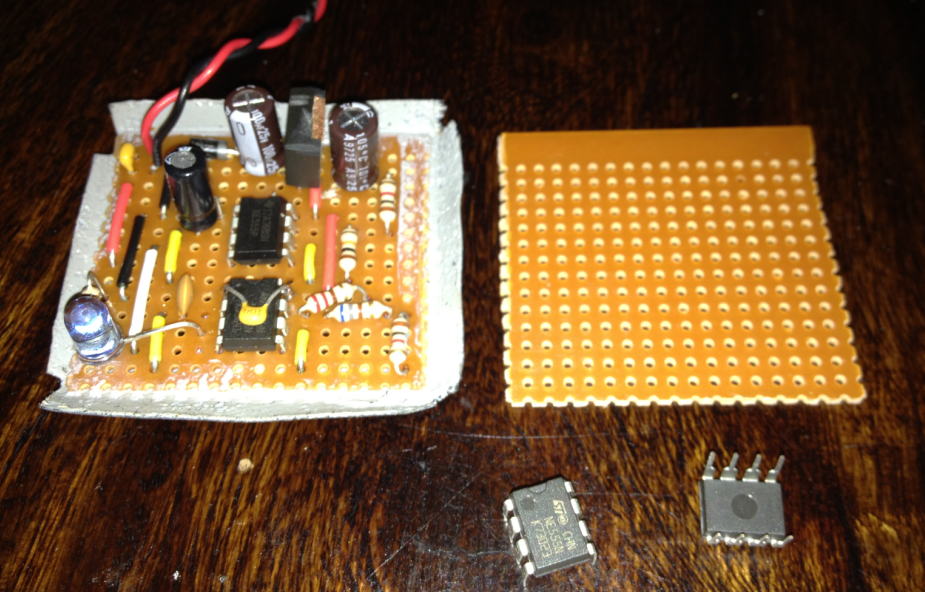
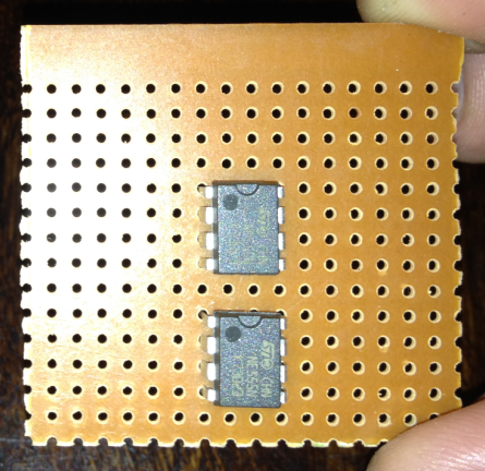
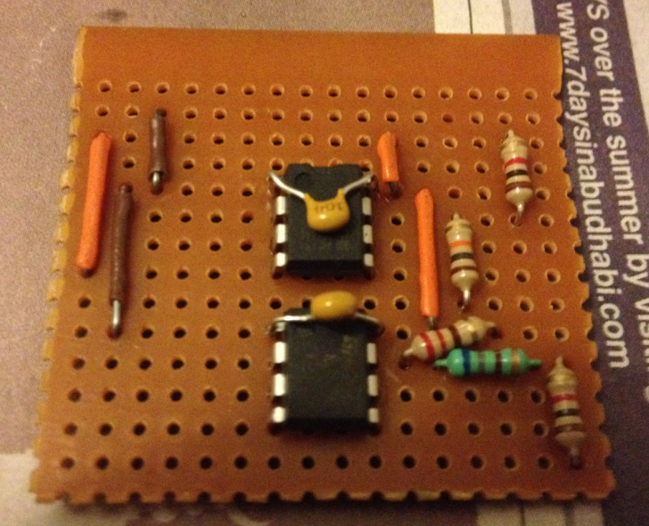
1) Placing The 555 Timers
 Place the two timers with the notch facing the top of your circuit. Leave four rows of space above the top timer, one row between the top and the bottom and you should be left with one more empty row below the second timer.

The timers should be placed with six free columns on either side. See the picture for reference.

Important: The copper tracks on your strip board should be running from left to right confirm this before soldering.

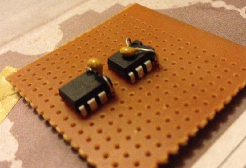
2) Add Decoupling Capacitors
Add a 0.1uf ceramic capacitor as a decoupling capacitor across pins 1 and 8 (top left and top right) of each 555 Timer. I have soldered mine directly to pins 1 and 8 to save space.

 3) Add Positive Power
Add the connections to positive power.

When we add the 7805 regulator in a later step, the third row (counting from the top) will be our 5 volt power supply rail. Connect this to PIN 8 (top right) of both 555 Timers.

In this case I am using orange wire for the connections to the 5 volt power rail.

At this point we can also connect PIN 4 (bottom right) of the top 555 Timer to 5 volts. This is the reset pin, it is active low, so by connecting it to +5volts we ensure that the timer is never reset.
4.1) Add Ground Connections
4.2) Add Timing Resistors
Two steps in one here -
1) Add ground connections. Pin 1 (top left) of each 555 timer needs to be connected to the ground power rail. When we add the 7805 regulator, the second row (counting from the top) will be ground, connect this row to Pin 1 of each timer, I have used brown wire for this connection in the picture.

2) Timing resistors -
Now we add the first of our timing components. In order from top to bottom we add a 1K resistor (brown,black,red) from the 5volt power rail (third row down) to pin 7 of the top 555 Timer. Next we add a 10K resistor (brown, black, orange) from the same pin 7 to the row which we left free between the two 555 timers. The final resistor is a 1K (brown, black, red) resistor connected from pin 7 of the bottom 555 timer to the very bottom row of our board.

5) Add Timing Resistors Continued
Next we need to add two more resistors to the second timer.

Connect a 220 resistor (red, red, brown) from pin 8 to pin 7 of the lower 555 timer.

Connect a 680 resistor (blue, green, brown) from pin 7 to pin 7. Yes, thats right from pin 7 to 7, its the blue resistor in the picture and for it to have any effect we need to cut the copper track beneath the resistor. Its also a good opportunity to mention that we need to cut the tracks which would otherwise connect the 555 timer pins left to right. Refer to the picture later in the post.

6.1) Add Timing Capacitors
6.2) Add Timing Connections
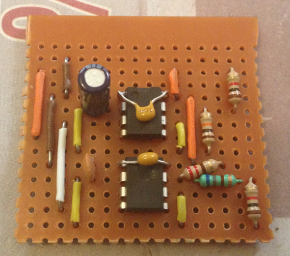
Add the 1uf electrolytic capacitor (big black can) between pins 2 and 1 of the top 555 timer. Note that these capacitors are directional, there is a strip with a minus sign printed on it which indicates which side should connect to ground (pin 1) in the picture the strip is facing away from the camera. The other side is connected to pin 2.

Next we connect the 0.01uf ceramic capacitor between pins 1 and 2 of the lower timer. This capacitor is not directional.

Finally we need to add connections between pin 2 and 6 (trigger and threshold) of the timers. In the picture I have used yellow wire for this, it would have been possible to route the wire directly across the chips from pin 2 to 6 however in this case I have chosen to route two wires, one down from pin 6 to the empty row immediately below the chip and one back up from from the empty row to pin 2. Repeat this for each of the two timers.


Electrolytic Capacitor Orientation
Larger value capacitors tend to be available as electrolytic capacitors, these have an appearance something like a can. Electrolytic capacitors are directional, to ensure that they are correctly placed, the cans have a band marked with a minus sign to indicate the side/pin which should be connected to ground.


7) Connect The Timers Together
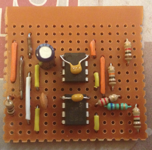
 This one is easy. We want to connect the output of the first timer (top) to the enable of the second timer (bottom).

This allows the top timer which is running at 1000hz to switch the bottom timer on and off to generate our coded 38Khz signal.

This connection is shown by the white wire connecting pin 3 (output) of the top timer to pin 4 (reset) of the bottom timer.
8) LED Current Limiting Resistor
As with any LED we need to limit the current passing through our infra red LED. As we are pulsing the LED it is only on for very short durations and so we have the option of passing more current through it. In this case I am using a 100 Ohm resistor (brown, black, brown) to limit the current to 50 milli amps, you could use a lower resistor for more power which would give a greater lap detection distance however on a narrow RC Track which loops back on itself a 100 Ohm resistor is perfect.

The 100 Ohm resistor is connected from pin 3 (output) of the lower 555 timer to pin 1 (ground). In the next step we will add the LED and cut the track between pin 3 and the resistor.

9) Double Check
Its a good time to double check progress. Here is the circuit constructed so far shown from the left side, double check yours against this and the previous images.


10) Add The IR LED
Not a great picture, but its an easy step.

Like all LEDs, the infra red ones are directional. This means the LED will only light if connected the correct way. As we cannot see infra red, its worth a little extra explanation to make sure we get this part right.

Most LEDs have on leg which is longer than the other, the long one should be connected to the positive (closest to the chip) and the short to negative (the path to ground is provided by the 100 Ohm resistor). However I have recently bought a batch of LEDs where the legs were cut incorrectly. To double check you LED placement, look at the inside of the LED you should see to metal plates which are roughly triangular. The smaller of the two plates is the positive side of the LED and should be connected nearest to pin 3 of the bottom timer. The other leg should be connect next to the 100 Ohm resistor where it joins the same row as pin 3. You will need to leave at least one spare hole in the board between the LED legs, you will need to bend one of the legs into an S/Z shape to do this.

As both ends of the LED are connected through the strip of copper running from the resistor to pin 3, we need to cut the copper strip to force the electricity to pass through the LED. Cut the track in the spare hole you left between the two LED Legs - refer to the underside picture for reference.

Almost Finished !
The original transponder design is finished here and if you intend to use the transponder for motor racing or kart racing, just add a positive power connection to row 3 (third row down counting from the top and linked to the orange positive power wires) and a ground connection to row 2 (second row down connected to the brown ground wires).

Add a 9 volt battery or even better 4 AA Batteries and go racing !

If you intend to use the transponder in an RC Vehicle and want to share the RC Power you will need to buffer your RC Receiver from the switching noise generated by the 555 timer. The most effective way I have found to do this is by using a 7805 regulator.

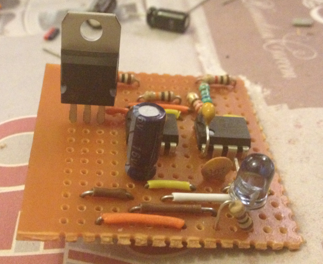
11) Adding The Regulator
The 7805 regulator prevents the switching noise in the transponder circuit from being transmitted through the power circuit and into your RC Receiver.

For the regulator to function it also needs two capacitors as supporting components which we will add in a later step.

For now place the 7805 regulator in the 10th hole counting from left to right. The regulator should be orientated so that the heat sink is on the right side of the circuit and the legs point down towards the 555 timers.


You might want to cut the heat sink off the 555 timer, this makes it easier to mount in your cars window, do this before soldering so that you do not damage the circuit while cutting.


13.1) Add The Capacitors
13.2) A Diode
13.3) Power Connection
Lets do this in the order in which power enters our circuit.

1) Solder your positive power wire ( the red wire) to the very top row of the circuit, is the top left most hole.

2) Solder your ground (black wire) connection to the second row, if we have followed the steps correctly this should also be the same row as the middle pin of the 7805 regulator.

3) Connect a 0.1uf decoupling capacitor between the positive and negative power rails, in the picture you can see that I added mine to the left of the wires, you can add yours to the right as long as its immediately next to the incoming power connections.

4) Add a diode. Diodes are directional components, they only conduct electricity in the one direction, the direction is indicated by a band printed on the diode. In the picture the silver band indicates the direction in which electricity is allowed to flow. The band is facing the 7805 regulator meaning that electricity can flow into our circuit but if electricity is connected in the reverse direction the diode will prevent it from flowing and damaging our circuit.

The diode is connected to the positive power track at the top left of our circuit, once we cut the copper track underneath the diode the electricity will have to travel through the diode to reach our circuit. If we accidentally connect power in the wrong way, the diode will prevent damage to the rest of the circuit from the reverse power.

5) Add the 7805 Supporting capacitors. In order to regulate the power to our circuit, the 7805 requires some additional external components, in this case we are using two 100uf electrolytic capacitors. Like all electrolytic capacitors these are directional components, a band on the capacitor indicates the side which should be connected to ground. The middle pin of the 7805 is the ground, it should be soldered in the second track down on our board which will be the ground rail. The outer pins are the input power supply and the 5volt regulated output, each of these should be connected to the center ground pin through one of the 100uf Capacitors - make sure that the band indicating the negative side of each capacitor is connected to the center ground pin of the 7805.

Final Steps
Our final step is to cut the copper tracks under the 555 timers so that the left and right pins are not shorted together, a 3mm drill bit will do this nicely.

Final checks and trouble shooting -
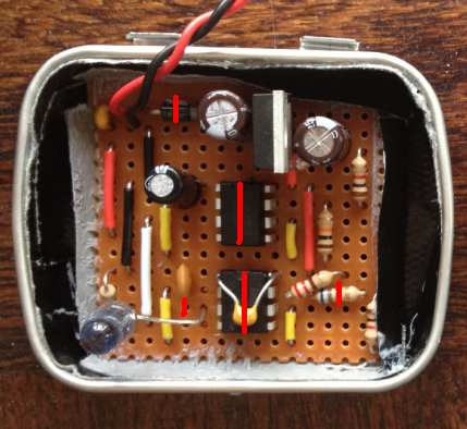
1) The copper tracks on the underside of the circuit should be cut in the following locations -

In the picture the copper tracks are running from left to right across the underneath of the board. The red marks indicate where a track should be cut, in order from top to bottom these points are -

Diode - We need to cut the track directly underneath the diode in the top left of the circuit, this will force the electricity through the diode ensuring that if we connect power the wrong way around, no electricity will flow and no damage will occur.

555 Timers - We need to cut the tracks between the left and right pins or the two timers, this means 4 cuts on the first time and four on the bottom so that the pins are not shorted by the copper tracks.

680 Ohm Resistor - This resistor is connected to pin 7 of the second (lower) 555 timer and runs horizontally along the board. As this is the same direction as the copper tracks under the board, we need to cut the track under the resistor otherwise the electricity will by pass it through the copper track.

IR LED - This component is also connected horizontally across the board. In order for the electricity to pass through the LED we need to cut the track between its two legs, in the picture the cut is marked one hole to the left of where the positive leg of the LED is soldered next to pin 3 (output) of the lower 555 timer.


2) Confirm that all of the components are correctly orientated.

3) Test the circuit - in order to test the circuit we need an IR Detector, a simple test circuit is provided in the following link, if you can light the red LED with the signal from your transponder, well done you have a working transponder.

http://learn.adafruit.com/ir-sensor/testing-an-ir-sensor

Additional References -

NE 555 Datasheet with pinout
http://www.ti.com/lit/ds/symlink/ne555.pdf

7805 Regulator Datasheet
http://www.sparkfun.com/datasheets/Components/LM7805.pdf

Next time - Adding the IR Detector to our lap timer circuit.

Bonus Step -

As an optional step you might want to consider adding the amplifier circuit shown here -

http://rcarduino.blogspot.com/2012/08/adding-audio-to-arduino-projects.html

The external audio mode can be switched on and off through the lap timer menu for extra volume when you need it. The new lap time countdown mode that you can hear in the video can also be switched on and off through the system menu.


External Audio and best lap time countdown demo -


 Stay tuned ...

Duane B

Sunday, August 26, 2012

The Must Build Arduino Project - The Illutron B

Is there a must build Arduino project ? Something simple that can be built in minutes and tinkered with for days or weeks ?

There is now.

Presenting the Illutron B -


The Illutron B is a development of the Illutron synthesizer originally created by Nikolaj Mobius. All of the sound in the clip is being generated by the Arduino with no outside assistance or post processing - the bass notes are extraordinary.

Even more incredibly is that all of the sound is being generated using just one analog output.

How does it work ?
If you think of an analog output as a power switch, the longer it is switched on, the more power we output. By varying the duration that the power is on over time we can output a waveform, for example a sine wave.

Its a technique known as Direct Digital Synthesis. The is a good example here http://interface.khm.de/index.php/lab/experiments/arduino-dds-sinewave-generator/


Taking it further - Skip the theory if you like, or read on -
The Illutron B is a wave table synthesizer, this is a synthesizer which uses the Direct Digital Synthesis described above to generate sound waves using descriptions 'wave tables' that are stored in the memory. 

The wavetables are simply arrays, if you take the values from each of the wave header files and copy them into your favorite spreadsheet you will see the following - 


Synth designers know that as listeners we do not find endlessly repeating sine, square or triangle waves very interesting. To make the sound more musical wave table synthesizers combine the waveform with an envelope. 


The envelope describes the power or loudness of the waveform over time - think of a snare drum, its starts very powerfully and decays away to nothing very quickly - a flute can start softly, reach a level then decay softly - its the envelope that describes this. The simple trick of combining the wavetable with an envelope is responsible for the huge range of musical possibilities in wavetable synthesis.

How do we do this in software ? - It couldn't be easier, we mulitply the waveform by the envelope, as the envelope value gets smaller, so the output waveform shrinks away to nothing.

Have a look through the code, its extensively documented.

Built in envelopes - the faster the sound drops away, the more percussive (drum like) the envelope -


You can add your own envelopes, or modify the supplies ones, there is no rule that an envelop cannot start quietly and get louder - or look like a heart beat for a pulsing bass sound.


Build your own pocket night club -

How long does it take to build ? anywhere from 5 to 10 minutes, seriously, if you have two potentiometers a few capacitors and resistors you can be playing your own Illutron B in 10 minutes.

What does it do ?

While the synth is very powerful, Nikolaj has included a demonstration tune which is the basis of the clip.

In the clip I am using the Illutron B which provides control over the beats per minute and also the pitch of one of the four channels using just two potentiometers to jam with the demo tune.

This is where RCArduino comes in. When I first heard the Illutron I was blown away, it is far and away the best Arduino Audio project of all. The drum sounds are awesome, the bass is incredible, you will not get tired of exploring those low notes. I know that as a community we can make great things from this.

For this reason I have spent the past few days refactoring, optimizing and documenting the Illutron version B.

Some ideas for your own Illutron projects -

1) Hook up some peizo knock sensors for an electronic drum kit
2) Bass loop generator with push buttons for different bass drops
3) A four channel sequencer
4) Sound effects for games, installations and robots
5) Its a great basis for a Thermin or similar physical instrument.
6) Add some soft pots, cross faders or a stylus to control the pitch of the different channels

Nightclub in your pocket

My own idea is to build on the current example - Ideally I would like to see a set of beats or tunes included in a 'Night club in a box' where the user can select the beat with a push button. The user is then free to jam with the selection in the same manner as the video - Arduino, two potentiometers, one resistor, two capacitors, synched LED Light show and you have an instant pocket night club that everyone can enjoy.


In order to support the further development of Nikolaj's original concept I have refactored the original Illutron code into a more user friendly class library while at the same time taking the opportunity to do some optimizing and improve the readability of the code.

If you would prefer to use Nikolaj's original code for the Illutron Wave Table Synth, its available here - http://www.instructables.com/id/Turn-your-Arduino-into-a-4-voice-wavetable-synth-w/

The Illutron B code is being added to the Illutron repository on github I will provide a link once its uploaded,  in the meantime, you can get it from me - DuaneB on the Arduino forum.

If your a musician it should be immediately obvious how to setup and trigger the different voices, the sample sequencer is also easy to understand and modify. If like me you are not a musician, build one anyway, the demo tune is great to play with and I hope to get some new tunes included for you to upload.

Whats an Illutron ?

Its actually an art studio on a ship in Copenhagen harbour. The original Illutron synth was created by a member of the Illutron collective Nikolaj Mobius. You can find out more about Illutron and their work in light, sound, electronics and a surprising amount of fire here - http://illutron.dk/posts/54


Building your own Illutron B - 

The easy part - 
2 * 10 K Potentiometers
4 * LEDs (or eight if you like)
4 * LED Current Limiting Resistors (500 to 1000 Ohms should be fine)

The only slightly less easy part -

Jelly Beans

What are Jelly Beans and why do I need them ?

Jelly Beans are those common components that all circuits need and you should have a jar full of. If your just starting out, you might not have these, but get some, they are very cheap standard components which are widely used in all sort of circuits.

1 * 2.2K resistor (or two 1K resistors in series - anything thats close)
1 * 0.1uF capacitor - you should have hundreds of these, they are used for stopping interference from other components from reaching the sensitive parts of your circuits, if you don't have any, buy 20, they are cheap and you will use them for everything.
1 * 100uf  capacitor - again these are widely used. In this case the capacitor is there to filter out a DC voltage so that your Audio equipment only receives the alternating signal part of the Arduino output. If you don't have any of these, get 10.

Here is the Schematic -

Note : The Fritzing software used to draw the circuit labels C2 with 0.1mF, this is the 100uf capacitor, 100uf is the most common way to represent this value but 0.1mf is also correct (1uf = 0.001mf so 100uf = 0.1mf)

You can also follow the original build instructions here -http://www.instructables.com/id/Turn-your-Arduino-into-a-4-voice-wavetable-synth-w/

Here is mine as used in the video. For the nightclub in a box project I will be adding two amplifiers based on the previous rcarduino post - Adding Audio To Arduino Projects - http://rcarduino.blogspot.com/2012/08/adding-audio-to-arduino-projects.html


The final part of the build to to plug the Illutron B into your MP3 Player docking station - I used a section of head phone cable soldered to a three pin header for this -


The code is now available for download on the RCArduino downloads page here -

http://rcarduino.blogspot.ae/2014/02/rcarduino-downloads.html

If you have any problems with the download, contact me 'DuaneB' through the Arduino forum or leave a comment.

In a future post I will explore more of the capabilities of the Illutron B, the Illutron team will also be working on new Illutron synth based projects.

Stay tuned

Duane B


Sunday, August 19, 2012

Adding Audio to Arduino Projects

Sometimes a project just needs to be louder, whether its a synthesizer, alarm clock, autonomous robot or the RC Arduino lap timer.

In the case of the lap timer, I want people in the club house to know when a lap record has been broken, it all adds to the pressure and the fun of racing.

One incredibly simple solution to getting more sound from a micro controller is the LM386 series of amplifier chips. These can give project quality audio for less than a dollar.  They even make a passable one dollar MP3 docking station and are the basis of the 'little gem' guitar amplifier.


LM386-N4 Big Audio In A Tiny Package - 

Parts List - 
1 x LM386-N4
2 x 100uf Electrolytic Capacitors
1 x 0.1uf Capacitor
1 x 100Ohm Resistor
1 x 10K Potentiometer

Circuit pictured is used to drive a PC Speaker in the RCArduino Lap Timer project - See the video.


The LM386 Minimal Components Circuit

The datasheet for the LM386-N4 which I am using provides some example circuits but these require non standard capacitors - by non standard I really mean that most of us keep 'decade' capacitors meaning the tens - 0.01uf , 0.1uf, 1uf, 10uf, 100uf. The sample circuits require 250uf and 0.05 uf capacitors.

As I didn't have these values, I built the sample circuits with 100's in series and 0.1's in parallel to get 200uf and 0.05uf. After playing with the circuit for a while I removed the series and parallel capacitors leaving just a single 100uf and one 0.01 uf capacitor. This variation of the recommended circuit works perfectly well, and is now included in the built version of the RCArduino Lap Timer.

So for a super simple chip to add quality sound and volume to a project order a few LM386N4's its amazing how many projects can benefit from bigger sound when its as easy as this.


Simplified LM386N4 Circuit To Drive PC Speakers From A Micro controller

Caution : The new generation of 32 Bit ARM chips used by the Arduino Due are less able to sink and source current than the AVR Chips used in the 8-bit Arduinos. A number of users have reported burnt out DAC (Digital To Analog Converter) outputs while using the Arduino Due. It is suggested that a series current limiting resistor should be used between the Arduino Due DAC Outputs and external circuitry.

There are currently a number of topics covering the Arduino DAC outputs and pin protection in general on the Arduino Due forum - http://arduino.cc/forum/index.php/board,87.0.html

The circuit below shows a suitable circuit for 8-bit AVR Arduinos - UNO, Mega, Leonardo etc.


 Data sheet with alternative circuits and full application details -

http://www.ti.com/lit/ds/symlink/lm386.pdf

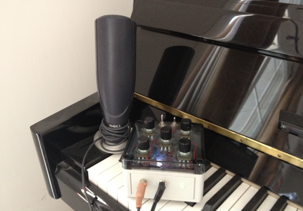
The RCArduino Five Dollar Synthesizer, Arduino audio played through the LM386 amplifier driving a PC Speaker

Project details here -
http://rcarduino.blogspot.com/2012/10/five-dollar-synthesiser.html


The Auduino
The five dollar synth is a great project if your up to re purposing an existing keyboard, if not, you really have to build an Auduino.

The Auduino is one of the best sounding Arduino Audio projects, it is also the easiest to build requiring only five potentiometers.
 
Update: The first video is my own Auduino, any others I post are enhanced Auduino's which for one reason of another are nicer than mine, so skip mine and have a look at what everyone else is able to get from this simple sketch through the use of clever additions -

My Own Audiuno - 
Totally standard Audiuno code with output direct to a PC Speaker using the LM386 Amplifier circuit shown in this post.


Auduino By DenkiTribe

A very musical Audiuno based jam -

The project enclosure seems to be closely related to a pizza box but we can forgive that for the very musical session. Modifications are obviously the stylus based pitch control and the addition of external echo.


Auduino By 'TheHangMansAxe'

As far as I can tell, thehangmansaxe has enhanced his auduino with two additions

1) An LED and LDR that 'gates' the output, for those of us with no audio background, gating is essentially connecting and disconnecting a signal from the output.

In DIY Projects LDRs are often used for this as they have an output which is a rough approximation to many stringed instrument where the initial note is loud but then decays away over time. LDRs initially react to light very quickly, but when the light is removed, they settle more slowly allowing the not to linger slightly.

At around the 1 minute mark the user shows the LED switching on and off through the side of the instrument.


2) Thermin style note sensing. The user does not provide any details, but I assume that the note is being controlled by infra red bouncing off the users hand. The original Audiuno design provided on tinkerkit uses five analogue inputs to control the sound, generally these are connected to puts but can also be replaced by any device capable of providing and analogue output.

UPDATE - 25/10/2012 - Added this section to explain how the Auduino works. It needs diagrams and rewritting for reduced length and increased clarity.


How does the Auduino work ?
While I am a big fan of the Auduino, its not that well documented. It is described as a 'granular synthesiser', I spent a lot of time reading up on granular synthesis and reverse engineering the code before I was able to understand exactly how the Auduino generates its particular sound.

A granular synthesizer is usually described as generating sound by rapidly repeating a small 'grain' of sound and if you read through the Auduino code you will certainly find repeated reference to grains however what and where are the grains ?

Outside of the Auduino project, the term grain is most often used to describe grains of sound which are sampled from real life speech, instruments or environmental sounds - a grain is a very short sample in the order of 1/10 to 1/10,000th of a second as opposed to the sampled vocal and drum tracks that you might be familiar with.

Pereshaped points out in the comments below that the synthesis technique used by the Auduino is closer to 'Vosim' that grain synthesis.
 
The Auduino code is actually very clever and efficient, instead of storing a grain the Auduino generates the grain in realtime using a simple counter.
The variables grainPhaseAcc and grainPhaseAcc2 are basically just counters. They count up, then down at a rate determined by grainPhaseInc and grainPhaseInc2. If you were to plot the value of these variables over time each one would give you a triangle waveform.

  // Increment the phase of the grain oscillators
  grainPhaseAcc += grainPhaseInc;
  grain2PhaseAcc += grain2PhaseInc;

The two variables grainPhaseInc and grainPhaseInc2 are directly controlled by two of the Auduino inputs. Adjust the potentiometers up and down and you will hear a frequency component of the output rise and fall in pitch as the relevant triangle wave increases and decreases in frequency.

These are not our main pitch control though, vary them up and down and while the quality of the note will change dramatically, the pitch of the note will stay the same.

The note pitch is controlled by the variable synchPhaseInc. This has an interesting job to do, it controls the rate at which yet another counter - synchPhaseAcc overflows. Whenever this counter overflows, it resets the the two triangle waveforms to an initial synchronized position. This periodic resetting of the two waveforms is what causes repetition of a repeatable 'grain' of sound. The rate of repetition gives the output its pitch.


Its actually a lot more interesting than that, what makes the Auduino sound so engaging is that as you increase or decrease the output frequency so you adjust the amount of the grain that is repeated adding additional layers of colour to the output tones.

The final stroke of genius in the Auduino design (its not my design so I am allowed to say this) is the use of the pentatonic scale. Instead of allowing you to choose any frequency you like the main pitch control is mapped to the musical scale know as the pentatonic scale. This is what gives the Auduino a kind of bluesy sound and ensures that you will never hit a duff note. For more on the pentatonic scale check out the wikipedia article.


A picture speaks a thousand works and Miro2424 has kindly posted this video of an Auduino in action on youtube. In the video you will see the two triangle waves superimposed on each other, you will see and hear how they are used to create both the pitch and the tone of the sound.


Auduino By Miro2424
I have been trying to learn how an 'addative', 'grain' or 'frequency on frequency' synthesizer like the Auduino works. This clip from Miro2424 shows the Auduino output visualised through what I am guessing is a high end PC Sound card. In the clip you can see the two triangular grains super imposed on each other and how they are used to create and vary the sound. Very happy to have found this, it makes it all easier to understand.


Everyone should have at least one Auduino, if you have a spare Arduino and 5 potentionmeters you can build one right now - http://code.google.com/p/tinkerit/wiki/Auduino

UPDATE - 01/02/2012
Here is another great variation on the Auduino by Moshang, this one also has the coolest name 'The Groovesizer' and also the best looking case of any I have seen so far.

The groovesizer extends the Auduino with a built in sixteen step sequencer.

Full details here - http://moshang.net/soundjeweler_blog/technique/groovesizer-diy-16-step-sequencer-and-synth/


UPDATE - 16/11/2012 - The Auduino is the original work of Peter Knight, the project home page appears to be inactive. RCArduino has previously reported a bug fix to the project which has not been updated. On the basis that the project is no longer active, a full version of the Auduino code including the bug fix and an added echo effect can be found on RCArduino -
http://rcarduino.blogspot.com/2012/11/auduino-with-delay.html
These two RC Arduino projects can also be built using identical hardware, upload them to your Auduino for a change of scene, you can always re upload the Auduino when your finished.

http://rcarduino.blogspot.com/2012/10/arduino-modular-synthesizer-part-one.html


Duane B