Showing posts with label RC Car. Show all posts

Friday, October 19, 2012

Lap Timer Build Along Part 4 - Adding the IR Detector

The final part of the lap timer build along is also the easiest part, involving only the IR Detector and an optional LED with current limiting resistors.

The previous steps can be found in the project index section of RC Arduino -
http://rcarduino.blogspot.com/p/project-index.html

A good introduction to IR Detectors is provided on the Ada Fruit website here -

http://learn.adafruit.com/ir-sensor

To start our build we need a small section of strip board and a set of three wires for power, ground and IR Out.

These can be soldered to the strip board so each leg of the IR Detector is connected through the copper strips of the strip board to one strand of the cable. In the picture I have used a section of ribbon cable, the cable should be long enough to suite your application, for example long enough to mount the detector on the steering column support of your Kart and allow you to attach the main unit to the steering wheel - don't make the cable longer than necessary it will only get in the way and may pick up interference.

Notice that the IR Detector is facing away from the connecting wires and that there is room for some additional components between the detector and the connecting wires, this is to allow us to add an indicator ID.

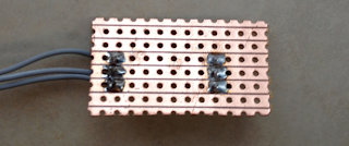
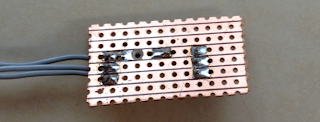
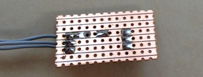
Reverse Side View

Next we add a 10K current limiting resistor between the output of the IR Detector and the wire we will be connecting to our Arduino interrupt pin.

For this resistor to have any effect we need to cut the copper track underneath the resistor so that the current has to pass through the resistor, a 3mm or 3.5mm drill bit will do this nicely.

Reverse view showing the cut in the copper track beneath the 10K resistor

Next we need to add the current limiting resistor for our indicator LED, I am using 560, but anything from 500 to 800 Ohms should be fine. This resistor connects from the row with the VCC Pin of the detector to the row below the Vout pin. From here we can also add two short lengths of connecting wire for our indicator LED, on wire should come from the VOut track and another from the track below VOut where we have just added the resistor.

This is to allow use to add an indicator LED which will light whenever the unit receives an IR Signal, this is useful as it will let you know if there is environmental interference such as reflected sunlight or fluorescent lighting.

At this point you should have the following circuit -
You can now add an indicator LED of whatever colour will be most visible in your application. To connect the LED, the long leg should be connected to the length of wire which is soldered to the same row as the 560 Ohm resistor, the shorted leg should be connected to same the same row as the Vout pin of the IR Detector.

You can test this set up immediately by connecting 4 to 6 volts to the circuit, the positive voltage should be applied to the top row, the ground should be connected to the middle row. If you use a TV Remote or the Transponder from part 3 of the build along, you should see the LED Light, if not, try swapping the LED around incase it was soldered in reverse.

This is essentially the same circuit as shown in the Lady Ada tutorial -

http://learn.adafruit.com/ir-sensor/testing-an-ir-sensor

Assuming that you have tested your detector correctly, we can now connect it to the Lap Timer.

To do this we need to connect the Vcc wire (top pin/wire in the picture assuming the detector is facing away from the connecting wires) to the 5V supply of the Arduino. Next we need to connect the center wire to the ground of the Arduino. Finally connect the bottom wire to digital pin 2 of your Arduino.

Congratulations, you have now finished the electronics however to be able to use the lap timer you need to build a small enclosure for the detector, without this sunlight and many type of indoor lighting will saturate your detector so that it is unable to detect signals. As I am based in Dubai where the sun is always fierce I have gone as far as spraying the inside of my enclosure with ultra matt camouflage paint. You can see the enclosures I have used in the following clips of the timer in action, not that the indicator LED is on the outside of the enclosure where we can see it - you knew that already right ?

Build Along Lap Timer in action complete with IR Detector as built in this post


I have recently added a few extensions to the project including a count down mode and support for external audio, you can see the new menu options and see them in action at the track in the following two clips -


New Menu Options
At the track with external audio enabled


The external audio option uses an LM386 based amplifier to drive external speakers. You can use this IC to add big sound to any Arduino project, here is a link to the circuit as used in the Lap Timer -

http://rcarduino.blogspot.com/2012/08/adding-audio-to-arduino-projects.html

If you would like the latest code, contact me through the arduino forum for a zip file containing the full project.

Future Developments - I am considering adding support for three additional transponder types -

1) Magnetic - I am told that many Kart Tracks use a magnetic strip under the track which lapping Karts detect using a window sensor such as you would use for home security.
2) Commercial Beacons - The commercial beacons used at many auto racing tracks use a well know pattern of pulses, it would make sense to support this pattern allowing users to 'arrive and drive' without having to place your own transponder around the track.
3) User selected pulse length - Allow the user to choose a pulse length, this would allow two or three systems to be used alongside each other. All of the calculations needed to build your own unique transponder are linked in previous parts of build along.

Stay tuned.

Duane B

Saturday, April 14, 2012

How To Read Multiple RC Channels

This post builds on previous posts to show a technique for reading multiple radio control receiver channels using an Arduino.

Update 27/03/2013 -  The Arduino Leonardo and Micro use the ATMega 32u4 chip which supports interrupts on fewer pins than the ATMega 328 used in Arduino UNOs and Minis. The pins used by the sketch have been rearranged so that the code can now be run the Leonardo and Micro as well.

If you have previously used the code, please ensure that you update your connecteds by swapping the input and output pins.


The following posts provide the necessary background to this post -

In the first post in this series we looked at the nature of an RC Receiver signal and provided a non blocking interrupt based approach for reading this signal with Arduino -

In the next post we looked at the Arduino servo library and how this allows us to generate the same signals that a radio control receiver generates. We can use this library to drive upto 12 servos or electronic speed controllers -
In the final post, we looked at the pinchangeint library which provides a convenient mechanism to access over twenty interrupts with a standard Arduino UNO. This overcomes the limitation of having only two external interrupts and allows us to use a standard Arduino to read more than twenty RC Channels -


Reading RC Channel Signals

Reading a single RC channel is relatively simple and can be outlined as -

1) Attach a pin change interrupt to the signal pin.
2) Create an interrupt service routine which will be called whenever the signal pin changes from high to low or low to high.

In the interrupt service routine we need to -

1) Check if the signal pin is high or low
2) If its high, this is the rising edge of the pulse, record the time using micros()
3) If its low, this is the falling edge. We are interested in the pulse duration, so if we call micros() to get the current time and then subtract from it the time we recorded in 2) for the rising edge we get the pulse duration.

The pulse duration calculated in 3) Above represents the input signal for the channel, refer to this post for a refresher - http://rcarduino.blogspot.co.uk/2012/01/how-to-read-rc-receiver-with.html

To attach the interrupt using the pin change interrupt library we call -

PCintPort::attachInterrupt(THROTTLE_IN_PIN, calcThrottle,CHANGE);

The interrupt service routine can be written as follows -

void calcThrottle()
{
  // if the pin is high, its a rising edge of the signal pulse,
  // so lets record its value
  if(digitalRead(THROTTLE_IN_PIN) == HIGH)
  {
    ulThrottleStart = micros();
  }
  else
  {
    // else it must be a falling edge, so lets get the time and subtract the time
    // of the rising edge this gives use the time between the rising and falling 
    // edges i.e. the pulse duration.
    unThrottleInShared = (uint16_t)(micros() - ulThrottleStart);

  }
}

So all we need to do is cut and paste the attachInterrupt and interrupt service routine code three times to read three channels ?

No. Its not that simple, but its really not very complicated either.

There are four considerations which apply when using interrupts -

1) Volatile Shared Variables
2) Variable Access
3) Fast Interrupt Service Routines
4) Timing

1) Volatile Shared Variables

When you upload a program with the Arduino IDE, your code will be compiled into an executable program that can be run on your Arduino. As part of this process the compiler will optimise the executable code to be smaller and/or faster. If we are not careful, this optimization can have unexpected results when using interrupts.

Example optimisations -

1) Replacing variables with constants
One of the optimisations a compiler will attempt is to look through your functions for any variables that are not being updated, the compiler can replace these with constant values.

2) Using registers to hold variables within functions
Another optimisation is to assign a variable to a register within a function rather than reading it from memory repeatedly.


The compiler makes optimisation decisions based on blocks of code, not entire projects. A common optimisation problem with interrupts occurs when a variable is updated in an interrupt service routine and read in the main code. Here the compiler may look at the main code and decide 'hey this variable never gets updated so I am going to replace it with a constant value'. In this case whatever the ISR does to the shared variable, your main code will never be effected because as far as the compiler could see, there was nothing that could update the variable within loop and so the executable code that was downloaded to you Arduino was generated to refer to a constant value - see 1) Above. 

A similar situation occurs when a variable is optimised to be held in a register rather than read from memory. One part of your executable code will be reading a value held in memory while another part will be updating a value held in a register. The end effect is that it appears as if your variable is not getting updated despite your ISR being called correctly and your code appearing correct - see 2) above.

Fortunately there is a keyword we can use in our code which tells the compiler 'never try and store this variable in a register, or replace it with a constant' the keyword is volatile. Any variables we wish to access from both our main code and an interrupt service routine must be declared volatile.

Really ?

Yes, I recently built an Audino, its an easy to build, fun to use synthesizer based on Arduino. The loop function reads five analogue inputs which control the sound. These variables are also used in a timer based interrupt service routine which actually creates the sound.

When I first built the project it didn't work. Reading through the source code I noticed that the analog inputs read in loop and used in the ISR were not declared as volatile. Adding the volatile declaration to these five variables fixed the problem.

Interestingly, the Audino has been around for years, it is likely that it worked perfectly with earlier versions of the Arduino compiler, but newer version may be optimizing differently. Whatever the case, the volatile keyword should always be used to tell the compiler not to optimize our shared variables.


In our code we must declare the channel input values as volatile in order that we can update them in the ISR and read them in loop -

volatile uint16_t unThrottleInShared;
volatile uint16_t unSteeringInShared;
volatile uint16_t unAuxInShared;


2) Variable Access

New Arduino programmers are often aware of the volatile keyword and assume that it is all that is needed to access shared variables. It isn't.

An interrupt service routine can be run at any point in your main code. Its called an interrupt because it interrupts your main code to do something else. This can lead to strange and difficult to trace errors if you do not control when your variables are being accessed.

How do these strange and difficult to trace errors happen ?

The simplest explanation is that if your main code is reading a variable when it is interrupted and the interrupting service routine changes the variable value, your main code will be left with part of the old value and part of the new value which is not what you intended or your code expected. This is often experienced as glitches blamed on hardware, but is in fact an easily solved software problem.

As a simple example a two byte integer changing from 256 to 255 in an interrupt service routine could be seen in loop as 511.

                                      Byte 1      Byte 2
Original value = 256 = 00000001 00000000
Updated value = 255 = 00000000 11111111

Loop reads byte 1 = 00000001

The ISR is called and updates the 2 byte integer from 256 to 255

Loop reads byte 2 = 11111111

Loop sees byte 1 + byte 2 as integer 0000000111111111 = 511

This unexpected value is a result of reading byte 1 before the interrupt and byte 2 after the interrupt. We must always ensure that our multi byte shared variables are read, updated or compared without any interrupts occuring.

To prevent this problem we need to ensure that whenever we are reading, writting or comparing a values larger than a single byte we cannot be interrupted until the operation is complete. The data types int, long and float are all multi byte data types ( int = 2 bytes, long = 4 bytes, float = 4 bytes) and therefore access must be controlled between the your main code and loop. The recommended approach to controlling access is to temporarily disable interrupts in order that your main code can perform a read, write or compare without being interrupted (remember the danger is that the interrupt will change part of the value that we have already read,written or compared in which case the results will be unpredictable and most likley lead to program errors - disabling interrupts for the read, write or compare prevents this).
  
To disable interrupts we call nointerrupts(), to enable then again we call interrupts().

// turn interrupts off 
noInterrupts();
    
    // Access your shared variables here ...

// finished with the shared variables, so turn interrupts back on
interrupts();

Note - While interrupts are disabled we will not be able to read incoming signals and this can effect our accuracy. See the example code where local variables as used to minimize the time that interrupts are disabled.
Using the status register directly vs interrupts() and noInterrupts()

Note - There is some criticism of noInterrupts and interrupts on the basis that the interrupts function reenables interrupts regardless of whether they were enabled or disabled before noInterrupts was called. This could cause problems where your code is called by a library which requires interrupts to be disabled. The preferred technique is to record the global status register, update the status register to disable interrupts, then restore it to its previous value - this maintains the status that was inplace before your code rather than blindly (and unsafely) restoring interrupts.

byte sregRestore = SREG;
cli() // clear the global interrupt enable flag

// Access your shared variables here ....

SREG = sregRestore; // restore the status register to its previous value


3) Fast Interrupt Service Routines

When an interrupt is triggered the microprocessor disables further interrupts before calling the interrupt service routine. While we are inside our interrupt service routine, we cannot process any new incoming events, therefore it is important for the accuracy of our input signal that we keep our interrupt service routines as short as possible.

As a guideline the interrupt service routine should record the occurrence of an event, but should not attempt to perform any extended processing in response to the event.

In our example of reading three receiver channels and outputting 3 servo signals we are processing 500 interrupts per second. The difference between an idle throttle and full throttle is only 0.5 thousandths of a second - timing is going to be important.

If we want our main code to process an event, we need some mechanism for the interrupt service routine to flag that an event has occurred, one option is the use of bit flags.

Bit Flags

We can use bit flags to signal to our main code that new information is available from an ISR. Bit flags take advantage of the fact that a micro processor can read a single byte without being interrupted.

How do but flags work ?

If we treat a byte as being made up of eight bits, b0 to b7, we can use each bit as a signal between our main code and ISRs.The bits have the decimal values 1,2,4,8,16,32,64,128 which we can use to set, test and clear the individual bit flags.

// These bit flags are set in bUpdateFlagsShared to indicate which
// channels have new signals
#define THROTTLE_FLAG 1
#define STEERING_FLAG 2
#define AUX_FLAG 4

// a single byte we can use to hold the update bit flags defined above
volatile uint8_t bUpdateFlagsShared;

to test, set and unset bit flags we can use -

// test to see if a flag has been set - use the bitwise AND operator &
if(bUpdateFlags & THROTTLE_FLAG)
{
   // flag was set ...
}

// set a bit flag - use the bitwise OR operator |
// set the throttle flag to indicate that a new throttle signal has been received
bUpdateFlagsShared |= THROTTLE_FLAG;

// clear a bit flag - use the bitwise XOR operator ^
bUpdateFlagsShared ^= THROTTLE_FLAG;


Bit flags provide us with a simple mechanism to communicate new events between the ISRs and loop. This is particularly important where we need to perform an extended calculation in response to the event. In the example code, we use the bit flag to tell loop that a new signal is available from a channel, loop then uses this information to updated the output for the channel.

4) Timing

We have already covered two of the issues which will effect our accuracy, we can add library functions for a more complete list as presented below -

1) Library functions that temporarily disable interrupts - some library functions will temporarily disable interrupts we cant control this but we can be careful about where we use these functions
2) Disabling interrupts in our own code - we will need to do this, but we can take care to minimise the time that interrupts are disabled.
3) Interrupt Service Routines - the microprocessor automatically disables interrupts before calling them and reenables them afterwards. Again we have to live with this but can be careful to minimize the time spent inside the ISR so that interrupts are enabled again as quickly as possible.

Putting it all together

The following code sample can be used to read three RC Channels through one set of Arduino pins and output those same channels on another set of pins. The code uses dedicated interrupt service routines for each channel, this is for clarity and could be changed to use a single interrupt service routine for all channels.

The code demonstrates the use of -

 - Bit flags to communicated events between the ISRs and Loop
 - Interrupt service routines to read rc channel signals
 - Enabling and disabling interrupts
 - Volatile shared variables
 - Taking local copies of variables to minimise the time that interrupts are disabled
 - Using the servo library to output RC Channels to servos or electronic speed controllers
 - Using the pin change interrupt library to access additional interrupts.

The sample code below the video was used in creating the video. A step by step guide to connecting the ESC, Steering servo, RC Receiver and Arduino will be provided in a followup post.


With two channels - throttle and steering - being read from the receiver and output to the car by Arduino


Sample Code - MultiChannels rcarduino.blogspot.com

// MultiChannels
//

// rcarduino.blogspot.com
//
// A simple approach for reading three RC Channels using pin change interrupts
//
// See related posts -
// http://rcarduino.blogspot.co.uk/2012/01/how-to-read-rc-receiver-with.html
// http://rcarduino.blogspot.co.uk/2012/03/need-more-interrupts-to-read-more.html
// http://rcarduino.blogspot.co.uk/2012/01/can-i-control-more-than-x-servos-with.html
//
// rcarduino.blogspot.com
//

// include the pinchangeint library - see the links in the related topics section above for details
#include <PinChangeInt.h>

#include <Servo.h>

// Assign your channel in pins
#define THROTTLE_IN_PIN 8
#define STEERING_IN_PIN 9
#define AUX_IN_PIN 10

// Assign your channel out pins
#define THROTTLE_OUT_PIN 5
#define STEERING_OUT_PIN 6
#define AUX_OUT_PIN 7

// Servo objects generate the signals expected by Electronic Speed Controllers and Servos
// We will use the objects to output the signals we read in
// this example code provides a straight pass through of the signal with no custom processing
Servo servoThrottle;
Servo servoSteering;
Servo servoAux;

// These bit flags are set in bUpdateFlagsShared to indicate which
// channels have new signals
#define THROTTLE_FLAG 1
#define STEERING_FLAG 2
#define AUX_FLAG 4

// holds the update flags defined above
volatile uint8_t bUpdateFlagsShared;

// shared variables are updated by the ISR and read by loop.
// In loop we immediatley take local copies so that the ISR can keep ownership of the
// shared ones. To access these in loop
// we first turn interrupts off with noInterrupts
// we take a copy to use in loop and the turn interrupts back on
// as quickly as possible, this ensures that we are always able to receive new signals
volatile uint16_t unThrottleInShared;
volatile uint16_t unSteeringInShared;
volatile uint16_t unAuxInShared;

// These are used to record the rising edge of a pulse in the calcInput functions
// They do not need to be volatile as they are only used in the ISR. If we wanted
// to refer to these in loop and the ISR then they would need to be declared volatile
uint32_t ulThrottleStart;
uint32_t ulSteeringStart;
uint32_t ulAuxStart;

void setup()
{
  Serial.begin(9600);
 
  Serial.println("multiChannels");

  // attach servo objects, these will generate the correct
  // pulses for driving Electronic speed controllers, servos or other devices
  // designed to interface directly with RC Receivers 
  servoThrottle.attach(THROTTLE_OUT_PIN);
  servoSteering.attach(STEERING_OUT_PIN);
  servoAux.attach(AUX_OUT_PIN);

  // using the PinChangeInt library, attach the interrupts
  // used to read the channels
  PCintPort::attachInterrupt(THROTTLE_IN_PIN, calcThrottle,CHANGE);
  PCintPort::attachInterrupt(STEERING_IN_PIN, calcSteering,CHANGE);
  PCintPort::attachInterrupt(AUX_IN_PIN, calcAux,CHANGE);
}

void loop()
{
  // create local variables to hold a local copies of the channel inputs
  // these are declared static so that thier values will be retained
  // between calls to loop.
  static uint16_t unThrottleIn;
  static uint16_t unSteeringIn;
  static uint16_t unAuxIn;
  // local copy of update flags
  static uint8_t bUpdateFlags;

  // check shared update flags to see if any channels have a new signal
  if(bUpdateFlagsShared)
  {
    noInterrupts(); // turn interrupts off quickly while we take local copies of the shared variables

    // take a local copy of which channels were updated in case we need to use this in the rest of loop
    bUpdateFlags = bUpdateFlagsShared;
   
    // in the current code, the shared values are always populated
    // so we could copy them without testing the flags
    // however in the future this could change, so lets
    // only copy when the flags tell us we can.
   
    if(bUpdateFlags & THROTTLE_FLAG)
    {
      unThrottleIn = unThrottleInShared;
    }
   
    if(bUpdateFlags & STEERING_FLAG)
    {
      unSteeringIn = unSteeringInShared;
    }
   
    if(bUpdateFlags & AUX_FLAG)
    {
      unAuxIn = unAuxInShared;
    }
    
    // clear shared copy of updated flags as we have already taken the updates
    // we still have a local copy if we need to use it in bUpdateFlags
    bUpdateFlagsShared = 0;
   
    interrupts(); // we have local copies of the inputs, so now we can turn interrupts back on
    // as soon as interrupts are back on, we can no longer use the shared copies, the interrupt
    // service routines own these and could update them at any time. During the update, the
    // shared copies may contain junk. Luckily we have our local copies to work with :-)
  }
 
  // do any processing from here onwards
  // only use the local values unAuxIn, unThrottleIn and unSteeringIn, the shared
  // variables unAuxInShared, unThrottleInShared, unSteeringInShared are always owned by
  // the interrupt routines and should not be used in loop
 
  // the following code provides simple pass through
  // this is a good initial test, the Arduino will pass through
  // receiver input as if the Arduino is not there.
  // This should be used to confirm the circuit and power
  // before attempting any custom processing in a project.
 
  // we are checking to see if the channel value has changed, this is indicated 
  // by the flags. For the simple pass through we don't really need this check,
  // but for a more complex project where a new signal requires significant processing
  // this allows us to only calculate new values when we have new inputs, rather than
  // on every cycle.
  if(bUpdateFlags & THROTTLE_FLAG)
  {
    if(servoThrottle.readMicroseconds() != unThrottleIn)
    {
      servoThrottle.writeMicroseconds(unThrottleIn);
    }
  }
 
  if(bUpdateFlags & STEERING_FLAG)
  {
    if(servoSteering.readMicroseconds() != unSteeringIn)
    {
      servoSteering.writeMicroseconds(unSteeringIn);
    }
  }
 
  if(bUpdateFlags & AUX_FLAG)
  {
    if(servoAux.readMicroseconds() != unAuxIn)
    {
      servoAux.writeMicroseconds(unAuxIn);
    }
  }
 
  bUpdateFlags = 0;
}


// simple interrupt service routine
void calcThrottle()
{
  // if the pin is high, its a rising edge of the signal pulse, so lets record its value
  if(digitalRead(THROTTLE_IN_PIN) == HIGH)
  {
    ulThrottleStart = micros();
  }
  else
  {
    // else it must be a falling edge, so lets get the time and subtract the time of the rising edge
    // this gives use the time between the rising and falling edges i.e. the pulse duration.
    unThrottleInShared = (uint16_t)(micros() - ulThrottleStart);
    // use set the throttle flag to indicate that a new throttle signal has been received
    bUpdateFlagsShared |= THROTTLE_FLAG;
  }
}

void calcSteering()
{
  if(digitalRead(STEERING_IN_PIN) == HIGH)
  {
    ulSteeringStart = micros();
  }
  else
  {
    unSteeringInShared = (uint16_t)(micros() - ulSteeringStart);
    bUpdateFlagsShared |= STEERING_FLAG;
  }
}

void calcAux()
{
  if(digitalRead(AUX_IN_PIN) == HIGH)
  {
    ulAuxStart = micros();
  }
  else
  {
    unAuxInShared = (uint16_t)(micros() - ulAuxStart);
    bUpdateFlagsShared |= AUX_FLAG;
  }
}

Coming soon - A walk through connecting the three radio channels to the Arduino and then the processed signals back out to a car, robot or other application.

Duane B

Wednesday, January 25, 2012

Extra Channels On The Cheap

Ever wanted to add an extra channel to your car, boat, robot ?

One of the guys commenting on the blog mentioned that he was working on a tugboat project. This brought to mind the one or two marine models that I have seen, from memory these models are very big on scale detail and moving parts.

This set me to thinking what could a micro controller do in this environment ?

Something very quickly came to mind that could be used in this application or any other where you would like to add one or two 'toggle' channels to a model. These are channels that are either on or off, and are ideal for setting off signalling sequences, turning lights on and off, switching mix modes remotely, activating a scale winch or basically any other application you can think of that requires the ability to remotely switch something between two states or positions.

This is a very simple trick which I have used to remotely toggle between dad mode and child mode in one of my projects. The trick is to use the small zone between neutral throttle and the point at which the motor overcomes stall inertia.

If neutral throttle is a pulse of 1500, you can use 1510-1525 to toggle one action and 1475 to 1490 to toggle another action. The values may need adjusting in particular applications, but the concept is the same -


If the throttle is held in this region, switch an indicator light on and take a time stamp.

If the throttle moves out of this region, switch the indicator light off and clear the time stamp.

If the throttle remains in the region, check the time stamp against the current time, if the difference exceeds your switch period, then toggle your mode/lights/winch whatever.


Its the method I use to switch modes in the child mode project, its incredibly useful to be able to switch parts of your code on and off remotely while the model is running. But the same approach applies equally well to all sorts of scale model applications such as I have suggested above.

As we are using the stall space around neutral, our model will not be moving, so there is no reason why we could not combine this with the steering channels to add even more channels.

By my calculation using throttle and steering channels gives 2 (up,down) * 3 (little left, little right, centered) = 6 on/off channels.


How much do these extra toggle channels cost ? An Arduino UNO is around 20 GBP but you can assemble your own from components for 7 GBP and the best part is the Arduino can do a lot more than just switch something on and off, any one of those six toggle channels could set off pre programmed sequences across multiple servos, lights, speakers and other actuators.

Simple Example - Toggling One Mode Using Throttle Channel

  if(nThrottleIn <= THROTTLE_THRESHOLD && nThrottleIn >= (THROTTLE_THRESHOLD-20))
   {
     unsigned long ulCurrentCounter = millis();
     if(ulModeSwitchCounter == 0)
     {
       ulModeSwitchCounter = ulCurrentCounter;
     }
     else
     {
       if((ulCurrentCounter - ulModeSwitchCounter) > MODE_SWITCH_DURATION)
       {
         
ulModeSwitchCounter = 0;
          // SWITCH YOUR MODE HERE

       }
     }
   }


Duane B.


Friday, January 20, 2012

How To Read an RC Receiver With A Microcontroller - Part 2

If you read 'How To Read an RC Receiver With A Microcontroller - Part 1' you will probably have guessed that my approach is based around interrupts, you may even be thinking 'So what, there is nothing new in any of this'.

Your right on the first part, but writing the code to take control of the throttle signal on my 40Km/h RC Race car was a very long way from reading a signal and writing it to the serial port.

What Could Possibly Go Wrong ?

The real world quickly gets in the way - underground cables, vibration, noise from the RC Components in the car, mobile phone transmitters, the built up environment, low transmitter batteries, even passing traffic effects the signal.

During the design and test of the code, I had two hardware problems with a dry solder joint on the power capacitor attached to the electronic speed controller and a track on my low quality strip board which crumbled away. At the time I was not aware that these hardware issues were the cause and so I investigated every conceivable cause of interference.


Power Capacitor Soldered to ESC Power Terminals
Strip board track repaired after crumbling away!


One simple test repeated since the hardware issues were resolved involved propping the RC Car wheels off the ground and then walking away from the car with the transmitter. I repeated this many times, increasing the distance or changing the line of sight to include/exclude features in the built up environment. I was very surprised to see just how badly the signal degrades as you move the transmitter away from the car.


Transmitter and Receiver Adjacent To Each Other

Transmitter and Receiver 20 Meters Apart.


The charts show the pulse width variation over time with the transmitter set at a constant neutral signal. A straight line would indicate there is no variation in the pulse width, this is the result we might initially expect.

The two charts are generated using the code presented in the preceding post 'How To Read an RC Receiver With A Microcontroller - Part 1'


To create the charts, the serial output was cut and paste into Microsoft Excel.

The charts clearly show that as the distance between the transmitter and receiver increases, so the variation in the signal increases. My tests have shown that the built up environment has an additional effect, further compounding the effects of distance.


With no controller input and the transmitter positioned just 20 meters away, the signal output by the receiver would randomly wander by as much as 30 milliseconds either side of the transmitter signal. Some of this would be due to the built up environment, moving the transmitter to a position occluded by a steel reinforced concrete pillar would cause chaos in the servo at only 20 meters.

So this isn't going to work is it ?

Not only does it work, but it works brilliantly. The best thing I can say about using the Arduino to control the throttle signal is that you can't tell its there.

The first few times I drove the current version of the software I kept having to bring the car back in to check that I hadn't shorted something and bypassed the Arduino completely.

So how does it work ?

First of all the mechanical nature of the servos and motors in our equipment provides a certain amount of signal smoothing, put simply, they just cannot move fast enough to react to the variation in the signal and so their position at any point in time reflects an average value of the signal in the preceding milli seconds.

Sample signal variation over 1 second - a random walk around the value 1540 - the value output by the transmitter.


In addition to the smoothing provided by the mechanical nature of the car, I have included a 'confidence' algorithm in the code. This algorithm compares the current input to the previous output, if the variation is small it ranks the new signal with a low value, if the variation is larger, the signal scores a higher degree of confidence. If the signal returns to its original value the confidence is reset to zero. The basic concept is that if we receive a vastly different signal, the chances are that its a new command from the driver, but if we receive a series of wandering signals they can generally be ignored provided that they do not creep in one direction which would indicate a subtle but valid input from the driver.


// Confidence Version 2, smaller, better, faster ?

int nDifference = nThrottleIn - nThrottleOut;

 if(nDifference == 0)
 {
    nConfidence = 0;
 }
 else
 {
   nConfidence += (nDifference/4);
 }
  
 if((nConfidence >= SENSITIVITY) || (nConfidence <= -SENSITIVITY)) // SENSITIVITY = 8
 {
   nConfidence = 0;
  
   // do something with this pulse ....
 }


I am currently open minded as to the value of the confidence algorithm. Standard RC Equipment works well enough without the addition of this algorithm, however it is at a cost of battery drain, heat and mechanical wear. The real value of the algorithm in a mircocontroller environment is potentially in providing a lightweight, easily tuned mechanism to condition the signal for input into subsequent algorithms without introducing the lag that results from smoothing across multiple samples.

The following charts show a badly degraded signal before and after the simple confidence algorithm -

Signal Before Algorithm


Signal After Algorithm


In the charts above, the confidence algorithm clearly smooths a large amount of the signal noise, however it is too sensitive to cope with the extremes.

One feature of the algorithm is that the sensitivity can be easily changed through a single variable. 

Test Conditions 
The tests were performed with the transmitter and receiver at opposite ends of a steel reinforced concrete villa  -

The line of sight was occluded by at least two walls
The receiver was adjacent to and transmitting serial data to a laptop. 
The line of sight included an LCD TV and a kitchen appliance.

The reinforced walls, LCD TV and Kitchen Appliance have all been observed to cause a large degree of interference to RC equipment and signals. 

Ideally the tests should be repeated with a higher value sensitivity however the test conditions are extreme and do not provide any qualification of the algorithms real world usefulness.

At present the algorithm has very little performance impact and clearly removes some noise, however before the algorithm can be qualified into or out of the RC Arduino projects it will need to be tested in the two most common RC Applications -

1) Racing - This is a tough environment with multiple transmitters sharing a fairly narrow physical and electro magnetic space. 
2) Street Driving - This has its own challenges in the form of distorted signals reflecting from the build up environment.

In use to date, the confidence algorithm has no detrimental effect so it stays 'in' with one small change - 'Sensitivity' actually has the opposite effect and should really be renamed 'Damping' to reflect it effect on the signal variation.

Next up - Bad Pulses And What To Do With Them

How To Read an RC Receiver With A Microcontroller - Part 1

Its a very common question, 'How do I read an RC Receiver with my micro controller' and the answer is often very simple however the simple answer is close to useless in a real world application.

The approach outlined in this series of posts has been tested in an RC Race car running at 40+ Kmh at a range of 100 meters.

The approach is reliable, resilient, easy to understand and easy to modify. It has been tested using using 27Mhz AM radio equipment and entry level electronics. Use of better quality electronics and radio equipment will provide improvements in range and signal quality however as the development process has demonstrated, even low end equipment can be interfaced with Arduino for control of an RC Race car.

Update 05/11/12 Read multiple RC channels with a smoother, faster library -
http://rcarduino.blogspot.com/2012/11/how-to-read-rc-channels-rcarduinofastlib.html
For the background to this and the original sketch before optimisation see - 
http://rcarduino.blogspot.com/2012/04/how-to-read-multiple-rc-channels-draft.html


Update 04/11/12 - For those of you looking to read a PPM Stream instead of individual channels, I will have a small fast library up this week - will post an update with the link here -
http://rcarduino.blogspot.ae/2012/11/how-to-read-rc-receiver-ppm-stream.html


Background Information

What are we looking for when we read from an RC Receiver ? Its not what I originally expected, my guess was that it was an analogue signal that would be amplified by the speed controller or servo controller to drive the motors. Its not analogue at all, its actually mostly empty space.

Each channel decoded by your receiver is sent to your ESCs and Servos as a train of pulses, these pulses are sent about 50 times a second but the suprising part is, each pulse only lasts between one and two milliseconds (1/1000 to 2/1000 of a second). Before the next pulse arrives, there is a gap of 10 times the length of the even longest pulse.

In an Electric RC Car a pulse width of 1000 is full reverse or brake, a pulse width of 2000 is full throttle and a pulse of 1500 is neutral. Note that these may be reversed, but the nature and range of the signal does not change.

This pulse train as it comes from the receiver could not be used to drive anything, not even a toy motor. The ESC or Servo control circuitry takes the pulse train as an input and generates a very different output, not just in power, but also in profile and even polarity in the case of reversing a motor.


The Simple Approach and Why Its Wrong

A common suggestion is to connect the receiver to the microcontroler such that there is a common ground (GND) between the two devices and then attach the white or orange signal wire from the receiver to one of the digital input microcontroller pins.

From here there are a variety of approaches to reading the values from the pins -

PulseIn (a blocking polling approach)

PulseIn is a function available with the Arduino that implements an approach know as 'poling'. It essentially sits around waiting for something to happen, until something happens the rest of your code is blocked. This is okay for a simple lab exercise to read and print values from a receiver but it is a hopeless approach for a real world application. Fortunately there are better approaches that do not require a major learning curve.

Timers

There is an example in the Arduino Playground which uses timers ReadReceiver. It may offer greater resolution than the method I am using, but it is also considerably more complicated and as I will show in a follow up post, the source receiver signal degrades rapidly as you move outside the lab rendering the increased accuracy less valuable.

Interrupts

The Timer example and my own approach both use Interrupts. Interrupts allow you to declare your interest in an event and then have the micro controller 'interrupt' your code whenever the event occurs.

Lets take a closer look at the channel signal and determine which bits we should be interested in -


If all we are interested in is the pulse duration, why not use pulseIn ? after all there is nothing else of interest in the signal.

The Arduino UNO is able to perform 16 million operations in one second. In the 2 milli second duration of a full throttle pulse, the Arduino could have performed 32,000 operations ! Thats a lot of wasted power. But it gets worse, what if you call pulseIn immediately after a pulse, you will have to wait a whole 20 milliseconds for the next pulse to arrive and complete. Thats a full 320,000 operations useful operations your code could have completed.

On average you can expect to call pulseIn in the center between two pulses, this means that over an extended period, half or your available processing power is wasted just waiting for the next pulse to arrive and complete. If you add more inputs, the approach becomes quickly unsustainable as you can only give your attention to a single input at a time.

Don't Use Pulse In !

Here are some updates showing the code in action - 

Active Yaw Control Of An RC Race Car
http://rcarduino.blogspot.com/2012/07/rcarduino-yaw-control-part-2.html 

Mapping RC Car Controls To A  Tank Tracked Robot
http://rcarduino.blogspot.com/2012/05/interfacing-rc-channels-to-l293d-motor.html 


Using an interrupt to efficiently detect new pulses and output to serial

For reading multiple RC Channels see - 

http://rcarduino.blogspot.co.uk/2012/04/how-to-read-multiple-rc-channels-draft.html


// First Example in a series of posts illustrating reading an RC Receiver with
// micro controller interrupts.
//
// Subsequent posts will provide enhancements required for real world operation
// in high speed applications with multiple inputs.
//
// http://rcarduino.blogspot.com/
//
// Posts in the series will be titled - How To Read an RC Receiver With A Microcontroller

// See also http://rcarduino.blogspot.co.uk/2012/04/how-to-read-multiple-rc-channels-draft.html 

#define THROTTLE_SIGNAL_IN 0 // INTERRUPT 0 = DIGITAL PIN 2 - use the interrupt number in attachInterrupt
#define THROTTLE_SIGNAL_IN_PIN 2 // INTERRUPT 0 = DIGITAL PIN 2 - use the PIN number in digitalRead

#define NEUTRAL_THROTTLE 1500 // this is the duration in microseconds of neutral throttle on an electric RC Car

volatile int nThrottleIn = NEUTRAL_THROTTLE; // volatile, we set this in the Interrupt and read it in loop so it must be declared volatile
volatile unsigned long ulStartPeriod = 0; // set in the interrupt
volatile boolean bNewThrottleSignal = false; // set in the interrupt and read in the loop
// we could use nThrottleIn = 0 in loop instead of a separate variable, but using bNewThrottleSignal to indicate we have a new signal
// is clearer for this first example

void setup()
{
  // tell the Arduino we want the function calcInput to be called whenever INT0 (digital pin 2) changes from HIGH to LOW or LOW to HIGH
  // catching these changes will allow us to calculate how long the input pulse is
  attachInterrupt(THROTTLE_SIGNAL_IN,calcInput,CHANGE);

  Serial.begin(9600);
}

void loop()
{
 // if a new throttle signal has been measured, lets print the value to serial, if not our code could carry on with some other processing
 if(bNewThrottleSignal)
 {

   Serial.println(nThrottleIn); 

   // set this back to false when we have finished
   // with nThrottleIn, while true, calcInput will not update
   // nThrottleIn
   bNewThrottleSignal = false;
 }

 // other processing ...
}

void calcInput()
{
  // if the pin is high, its the start of an interrupt
  if(digitalRead(THROTTLE_SIGNAL_IN_PIN) == HIGH)
  {
    // get the time using micros - when our code gets really busy this will become inaccurate, but for the current application its
    // easy to understand and works very well
    ulStartPeriod = micros();
  }
  else
  {
    // if the pin is low, its the falling edge of the pulse so now we can calculate the pulse duration by subtracting the
    // start time ulStartPeriod from the current time returned by micros()
    if(ulStartPeriod && (bNewThrottleSignal == false))
    {
      nThrottleIn = (int)(micros() - ulStartPeriod);
      ulStartPeriod = 0;

      // tell loop we have a new signal on the throttle channel
      // we will not update nThrottleIn until loop sets
      // bNewThrottleSignal back to false
      bNewThrottleSignal = true;
    }
  }
}


Next up - Part 2 including what does the signal really look like ? and more of the code to deal with it.

For reading multiple channels using an interrupt driven technique see -

http://rcarduino.blogspot.co.uk/2012/04/how-to-read-multiple-rc-channels-draft.html

Thursday, January 12, 2012

Traction Control Part 1.3 - Childs Play.

EDIT: This has turned out to be really cool. Its great being able to take a car along on a walk with the kids,  drive it flat out and then be able to hand the controls to my two year old or three year old. All I have to do is hold the brake for a few seconds and the car will discretely switch into 'Child Mode'. Read on for details ...

If your a dad its great when your kids show some interest in any of your hobbies, but when a three year old takes control of your race car it can be a short lived and expensive experience.

Can I Have A Go ?


This is an open source project, based on open source hardware, but here is a project pitch anyway -

Wouldn't it be great if you could set you car to a lower 'child' speed even if it was at the other end of the park ?

You can now put your car into 'Child Mode' or back to 'Dad Mode' anywhere within range of your transmitter.

Turn RC Day into family day and protect your investment from children, wives and learner drivers of all ages !


There is no need to modify any of your existing components, just plug your receiver throttle channel into the Arduino and likewise connect your ESC to the Arduino.

Features
  • Remotely toggle between restricted power 'Child Mode' and full power 'Dad Mode'
  • Uses standard RC Equipment
  • No Modification of existing equipment required
  • Plug and play self calibration for quick changes between different models
  • Independently adjustable forward and brake/reverse power settings
  • 'Child Mode' Restricts the power available while still retaining proportional control through the full range of your controller
  • No additional RC Equipment required, takes its power from the existing car battery.


How does it work ?

The radio control equipment that steers and powers your vehicle uses on/off pulses to control the power and direction of your car. In general a pulse that is 1500ms wide is the center or neutral point, full throttle is around 2000ms and full brake or reverse is around 1000ms. These pulses are sent a steady 40 or 50 times per second, only the pulse width varies, not the frequency.

In standard 'Dad' mode, the Arduino reads the incoming signal and outputs a signal of the same pulse width to the ESC, the Adruino is effectively operating in straight through mode (blue line in chart below).


In 'Child Mode', the Arduino reads the incoming signal but generates an output signal based a scaling factor anywhere from 20% to 100%. The scale factor is separately adjustable for forwards and reverse, allowing any combination for example 50% forward power with full 100%  brake/reverse power (red line in graph) or 20% power in both directions (green line in graph).


Operation

The software is designed to start up in 'Dad Mode', as the car is driven, the software will monitor the maximum and minimum pulse width received in order to determine the full throttle and full brake settings.

How do you keep your paint as fresh as this ? Try 'Child Mode'
When the system switches to child mode, it will deliver only a percentage of the power available. The percentage delivered is determined through two rotary adjusters one for forwards power and one for reverse/brake power.The power delivery is scaled so that full proportional control is retained, for example if the power is set to 50% the system will deliver 50% of the input signal at 100% input, 45% at 90% input, 25% at 50% input etc. This allows the user to build experience in the proportional control of a performance model. As the user becomes more proficient, so the available power can be increased through the built in rotary adjusters.

To switch between 'child' and 'dad' mode, simply hold the brake for about 5 seconds and you will see the green child mode light indicating that the car is now in restricted mode. To return to standard mode, hold the brake again and wait for the light to go out.

The Circuit

The circuit is extremely simple using only the following components and Arduino PINs

  • Two LEDs with current limiting resistors as status indicators
  • Two variable resistors connected to two Arduino analogue inputs as the forward and reserve power adjusters
  • A single Arduino interrupt to read the incoming servo signal
  • A single Arduino PWM Pin to generate the outgoing servo signal
  • Power is from the LIPO battery in the car
The PIN assignments can be read from the code comments, the assigments are created through #define statements and so can easily be changed to suite an alternative layout.


Installed and road tested in my Tamiya M03 Race Car


The Code

The code is again very simple, whereever possible I have used meaningful names for variables and functions, its not that I like typing, I really dislike reading code, more typing now means less reading in the future.

The three novel features are -

1) EEPROM Error Log - I have a small 10 Byte area reserved in the EEPROM to record errors. Its round robin so will overwrite itself rather than overflow. On startup the software will send the 10 Bytes to serial to allow post run diagnostics if required, the log is cleared as it is sent so each run starts with a clear log.

2) Confidence - During my bench testing I noticed that the input signal as measured by the Arduino wanders around by +- 4 or 8 ms. If I treat each of these as a new command to the ESC, I get a lot of jitter. To smooth this and reduce the number of calls to Servo.writeMicroseconds, I have a very simple algorithm which maintains a 'confidence' level that an incoming signal is meaningful - its not very complex and is only designed to filter out random wandering around the current value.

3) Be bad, but not very bad - In early versions of the project the software would enter an error mode and put the car in neutral after receiving a single bad pulse. I have now introduced a bad pulse tolerance which allows the system to soak up noise that can't be avoided for example from crossing underground cables etc.
 

Further Development

For my purposes this project is a simple test of using the Arduino to interface between a hobby quality radio controlled car receiver and electronic speed controller or servo.

The project proves that -

1) It is feasible to read, process and output the throttle signal in realtime using the Arduino platform
2) Electrical noise can be managed so that it is not an issue

The next step for me is to implement 'active traction control' based on the wheel speed monitoring previously described in Part 1.1, however there are some potentially interesting further developments to this for example 'passive traction control'.

Passive Traction Control Project Suggestion 1 - Mulitple Acceleration Profiles


The existing code and circuit forms the basis for a passive traction control system. One simple project idea is to provide the car with different acceleration modes or profiles to suite different surfaces. The Arduino would read the desired throttle level from the receiver but would control the rate at which the output signal seeks the level of the input signal - on a dirt setting this rate of change would be low, on a tarmac setting a higher rate of change would be possible - this could be fine tuned in car using the existing circuit potentiometers.

Passive Traction Control Project Suggestion 2 - Brake Pressure Profiling


When a car is traveling at high speed, the brakes can be applied powerfully, however as the car slows down the brake pressure should be reduced to avoid the brakes locking up. This is a particular problem for RWD radio controlled cars which are prone to locking the rear wheels and spinning out under braking. In this project, the Arduino would monitor the input signal for maximum brake, it will initially output a maximum brake signal, but will begin to fade this signal for the duration of the brake command. The rate of fade and the target value - around 30% brake force for my M-04 could be adjusted in car using potentiometers. 

These two passive projects will be less effective than an active solution which monitors wheel speed however they are developments of the existing project that provide an incremental challenge. I will skip these developments and continue with the active version but feel free to use my code to explore these approaches.

The Hardware
The project is currently running an on Arduino UNO, this is a USB programmable version of the Arduino that costs around 20 dollars. This is an easy to use development board, but now that the code is finalised it can be run on a PCB or strip board based Arduino that is smaller, lighter and best of all can be built from components that cost less than 10 dollars.

Child Mode/Traction Control Circuit - Version 1

Top left - decoupling capacitors
Bottom left - mode and operational indicator LEDs
Center - Forwards and Reverse Child Mode max power adjustment
Right of center - connections for wheel speed sensors for all four wheels in traction control mode
Bottom right - 3 Pin headers for ESC Input and Output.

Child Mode/Traction Control Circuit - Version 2

Top Left - Power to the Arduino comes from the 8.4V Lipo battery in the car, it passes through this circuit on its way and is decoupled by the .01 .1 1 and 47 uf capacitors in the top left of the picture.
Top Left - Next to the decouplind capacitors are two strips of three pin PCB Headers, these are used to connect the throttle channel of the RC Car receiver to Arduino interrupt 0 and an Arduino output pin to the car ESC signal pin.
Bottom Left - The two potentiometers are used to adjust the amount of power the Arduino will make available for forwards and reverse throttle in child mode.
Top Center - Indicator LEDs, red for error, green for child mode and blue for a glitch or unexpected pulse that is within operating tolerance, its really an information signal telling me that the signal environment is dirty but not so much that we need to treat it as an error condition.
On the right hand side are the connections for the four wheel speed sensors. These are not used in the child mode project but are used in the ongoing traction control project.


Tuesday, January 10, 2012

The Uncontrollable Sand Scorcher Explained

Someone pointed out to me that its clear the Sand Scorcher has a lot of power in it from this picture.

 A lot of power putting a lot of sand in the air !

It turns out they were right. The low powered 'silver can' motor I installed was actually a much more powerful 19 Turn motor. Combined with the lightweight 25C Lipo battery was a bit much for the 30 year old chassis design.

Interestingly I was running the battery/motor combination through a standard Tamiya TEU104-BK Electronic Speed controller which survived the two or three runs it took me to discover the motor mistake.

Does this mean you can run a 19 Turn motor off the TEU-104 ?

No, I was lucky, you might not be. I will not be running this car again until I get the time to change the motor to either a Tamiya Sport Tuned or a Hobbywing 13 Turn brushless.

In the meantime I hope to road test part of the m-chassis traction control system this evening. I am a little apprehensive about moving this from the bench to road testing. This will be the first time I have run the car with the Arduino taking an active part in the control of the car, its a bit like 'fly by wire', there is no direct connection from the receiver to the speed controller, all speed signals are being sent from the Arduino.

Traction control update coming soon ...