
RCArduinoPersonalLapTimer by DuaneB is licensed under a Creative Commons Attribution-NonCommercial-ShareAlike 3.0 Unported License.
Based on a work at rcarduino.blogspot.com.
Update - I have three big ideas for a version 2.0 of the lap timer system, they build on the capabilities of version 1.0, extending its functionality to a completely new area and adding what I hope will be a really cool user interface feature.
Before I begin work on version 2.0 I am completing the Version 1.0 Build Along - Starting right now.
What do we get at the end of Part One -
- Record and review race and practice sessions of upto 500 Laps
- Scroll through summaries of each session to view best and average lap times and the number of session laps
- Scroll through individual laps within any session
- A bonus feature for part 1 only - The "Fake A Lap" button
- The "Fake A Lap" button allows you to test your build before we introduce the automatic lap capture features in - parts two and three.
- At the end of part one you will have a fully function manual lap timer - your very own self built multi lap, multi session stop watch !
Build this in Part One today (infra red lap capture in part 2 and build your own transponder in part 3)
Older posts covering the functionality, design and a demonstration using an RC Car can be found here -
Menu and RC Car Demonstration -
Features -
Interface Design -
Older videos -
| Timing an RC Car fitted with the transponder we will build in part three. |
A sample of the session and lap review menus
|
Everything in version 1.0 will be used as the basis for version 2.0. So lets get started -
Personal Lap Timer V1.0 Part 1
Goal - Build the user interface
Requirements - If you can grab a set of parts that looks like this, you can build part one of the lap timer in one hour.
 - An Arduino UNO or compatible (Arduino UNO recommended for beginners)
- An LCD Display
- A 10K Potentiometer
- Hook up wire, breadboard or strip board for connections.
- Four push buttons
- Four 10K pull up resistors for use with the push buttons
- If you want to add the 'Fake A Lap' button you will require one extra button, this button is not required in later stages.
About LCD Displays
There are several libraries for driving LCD Displays with Arduino including one which is installed by default as part of the Arduino application. This is the library we will use, it provides an easy to use interface for driving 'character' LCD displays. These are LCD Displays that already know how to show text and common characters. To keep things simple, the lap timer uses a very common 16*2 character display giving us two lines of sixteen characters to display our race and setup information.
If you do not have an LCD, most electronics suppliers will have them in stock. The approximate cost is 10 dollars or 7 Pounds, if you buy the LCD from a project orientated supplier they will tend to include a 10K potentiometer used to adjust the contrast and some headers for soldering.
LCDs are well known and commonly used components within the micro controller community, for two very good introductions see the links copied below -
Oomlout - A UK Based supplier with downloadable PDF tutorials (scroll to the end of the page) -
Adafruit - A US Based supplier with online tutorials -
Lap Timer Build Along Part One
Step One - Power Connections
1) Connect the red positive power wire from the Arduino 5V Pin to the red positive rail of the breadboard
2) Connect the black ground wire from the Arduino GND Pin to the black (mine is blue) ground rail of the breadboard
3) Check that there are no breaks in the breadboard power rail, mine has a break which I am connecting across using the short green and red wires in the picture below.

I am using a double size breadboard, but if you only have access to
smaller breadboards its not going to be a problem. See the two small red
and green wires in the picture ? They are there to connect the two
halves of this double breadboard together, you can do the same with two
smaller breadboards to make a larger prototyping area.
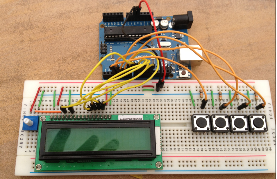
Step Two - Add The Buttons and Pull Up Resistors
1) Add your four push buttons, make sure to place them the correct way, in general push button pins are in a rectangular layout, the pins are connected to each other in the 'long direction'. The push buttons work across the short side, connecting and disconnect the short side as the button is pushed and released. In the picture the short side is pointing up.
 2) Add the 10K pull up resistors, here you can see that I am connecting the top right pin on each button to the red power rail through a 10K pull up resistor. When the buttons is pressed - as mentioned in 1) above, it will connect to the pin closest to it, this is what we want so in the next step we will be connecting the closest (top right) to ground. Note that the top right pin is permanently connected inside the button to the bottom right pin, this is a common mistake to make - the button is permanently on if you position it the wrong way.
Step Three - Add The LCD
1) If your LCD Has headers installed you can plug it straight into your bread board at this point, if not solder in the headers and then plug it in. If you do not have headers, you can solder jumper wires to the LCD and connect it this way. I often use cut off sections of old printer ribbon cables for these types of connections.

Step Four - Add Ground Connections to the buttons
 1) In step two we placed our four buttons (menu up,down,ok and cancel) and connected them through a 10K pull up resistor to the red positive rail of the breadboard. Now we want to connect the other side of the button to the black ground rail of the breadboard. Throughout the build along I am using red wire for positive connections and green wire for ground connections, it will make your own build easier if you follow a similar convention.
To understand why we are connecting the buttons this way, read any of the many Arduino Button Tutorials.
Step Five - Add The LCD Power Connections
1) We need to provide power to the LCD and the LCD Back light, to do this on most Arduino compatible LCDs we need to connect the outer two LCD connections to the ground rail and the connections immediately inside each ground connection to the red positive power rail. For alternative explanations of the same wiring refer to the LCD Links provided earlier in the post. There is one additional connection we need to make which is to connect the read write pin (R/W) to ground, we are only ever writing to the LCD so can hold this low. The end result whichever instructions you find easiest to follow should match the picture.

Step Six - Add The LCD Contrast Adjustment
As mentioned in the LCD Section at the start of the post, if you buy
your Arduino compatible LCD from a project orientated supplier they will
generally include a header for breadboard connections and a 10K
potentiometer to adjust the contrast. If you didn't get a potentiometer
with you display, any 10K potentiometer will do
 1) Connect the left pin of your potentiometer to the red power rail and the right pin to the ground rail of the breadboard.
2) Connect the center pin of your potentiometer to third pin from the left of the LCD - assuming your LCD Orientation matches the picture. I have used orange wire for this connection in the picture.
This connection allows us to adjust the contrast of the LCD, very useful in different light conditions.
Step Seven - Connect the LCD To your Arduino
1) Use jumper wires to connect the LCD Pins to your Arduino, on the Arduino side I am using digital pins 7,8,9,10,11 and 12.
2) On the LCD, these pins are connected as follows -
All LCD Pins are numbered counting from left to right starting with 1.

| Arduino PIN | LCD PIN |
| Digital Pin 12 | Register Select (Pin 4) |
| Digital Pin 11 PIN | Clock/Enable (Pin 6) |
| Digital Pin 10 | Bit 4 (Pin 11) |
| Digital Pin 9 | Bit 5 (Pin 12) |
| Digital Pin 8 | Bit 6 (Pin 13) |
| Digital Pin 7 | Bit 7 (Pin 14) |
The camera has fisheyed the picture slightly so it looks as if the connections on the left are one or two pins further left than they are. Follow the connections in the table and you will be fine.
Step Eight - Progress Check - Hello World
At this point you should be able to run any of the LCD Examples from the Arduino application. A good starting point is to check the connections with the 'helloworld' sketch. To do this -
1) Start the Arduino Application
2) In the File menu, select - Examples/LiquidCrystal/HelloWorld
3) You should now be looking at the example sketch 'HelloWorld' which is part of the Arduino download.
4) Find the line in the sketch that initialises the LCD Object, it should look something like the following -
// initialize the library with the numbers of the interface pins
LiquidCrystal lcd(12, 11, 5, 4, 3, 2);
This initialises an object named lcd of the class LiquidCrystal. As part of the initialisation our program is telling the object which pins to use. We want to use different pins, so we need to replace the line above with the following -
// Initialise the LCD using 12,11,10,9,8,7
// LiquidCrystal lcd(12, 11, 5, 4, 3, 2); // Original PINs
LiquidCrystal lcd(12,11,10,9,8,7);
// LiquidCrystal lcd(12, 11, 5, 4, 3, 2); // Original PINs
LiquidCrystal lcd(12,11,10,9,8,7);
Now upload the sketch and if you have connected everything correctly you should see Hello World and the time displayed on you LCD. If not, double check the connections and try again.
Step Nine - Connect Buttons and Finish
1) Connect the four buttons by connecting a jumper wire between the pull up resistor and the top left pin of each button.
2) The buttons should be connected to the Arduino as follows -
| Arduino PIN | Lap Timer Button (buttons from left to right) |
| Digital Pin 6 | Menu Up (Left Most Button) |
| Digital Pin 5 | Menu Down |
| Digital Pin 4 | Ok |
| Digital Pin 3 | Cancel (Right Most Button |
Step Ten - Upload
1) At this point we have completed Part One of the Lap Timer Build Along and can upload the Part One sketch to our build - I originally intended to include some test data so that at the end of Part One you would be able to use the system to scroll through some sessions and review the best, average and individual lap times within a session but then I thought - why not just add one more button ?
Bonus Step - The Big Red "Fake A Lap" Button
The lap timer uses infra red beacons or an infrared transponder to detect laps, we will get to detecting these in step two and building one in step three.
If we add one more button we can use the system as a manual lap timer right now on day one of the build.

2) Connect the button to the Arduino by adding a jumper from the button to digital pin 2. We are using interrupts to detect laps and so it must be digital pin 2.
The Code -
There are three files lapTimerBuildAlongPart1.pde, LapTimes.cpp and LapTimes.h
If it looks like a lot of code, it isn't, its mostly comments to explain what the code does.
LapTimerBuildAlongPart1.pde -
// RCArduinoPersonalLapTimer Part 1 by DuaneB is
// licensed under a Creative Commons Attribution-NonCommercial-ShareAlike 3.0 Unported License.
// Based on a work at rcarduino.blogspot.com.
#include <avr/pgmspace.h>
#include <EEPROM.h>
#include <LiquidCrystal.h>
#include "laptimes.h"
//*******************************************************************************************
// USER INTERFACE DEFINITIONS
//*******************************************************************************************
// initialise the liquidCrystal Library
// Initialise the LCD using 12,11,10,9,8,7
LiquidCrystal lcd(12,11,10,9,8,7);
// PINs for user interface buttons - use any
#define KEY_OK_PIN 6
#define KEY_CANCEL_PIN 5
#define KEY_UP_PIN 4
#define KEY_DOWN_PIN 3
// bit flags used in key functions getKeys, waitForKeyPress, waitForKeyRelease
#define KEY_NONE 0
#define KEY_OK 1
#define KEY_CANCEL 2
#define KEY_UP 4
#define KEY_DOWN 8
#define KEYPRESS_ANY B11111111
// display width + 1, used by getRamString to copy a PROG_MEM string into ram
#define DISPLAY_ROW_BUFFER_LENGTH 17
//*******************************************************************************************
// Lap Capture definitions
//*******************************************************************************************
#define LAP_CAPTURE_LED 13
#define BUZZER_PIN A0
// minimum and maximum duration of qualifying IR Pulse
#define MIN_PULSE_DURATION 200
#define MAX_PULSE_DURATION 500
// start and end of pulse
uint32_t ulStartPulse;
uint32_t ulEndPulse;
volatile uint32_t ulPulseDuration;
// flags to manage access and pulse edges
volatile uint8_t bIRPulseFlags;
//
volatile uint32_t ulNewLapStartTime;
#define IR_PULSE_START_SET 1
#define IR_PULSE_END_SET 2
//*****************************************************************
// Global Instance of CLapTimes class
//*****************************************************************
CLapTimes gLapTimes(new CEEPROMLapStore());
//////////////////////////////////////////////////////////////////////////////////
//
// doShowSessionSummaries
//
// implements the show session summary menu
// allows the user to scroll up and down through summaries of the recorded sessions
//
//////////////////////////////////////////////////////////////////////////////////
void setup()
{
Serial.begin(9600);
Serial.println("In Setup");
lcd.begin(16, 2);
lcd.print("Lap Timer");
lcd.setCursor(0,1);
lcd.print("Version 0.9 Beta");
delay(3000);
pinMode(KEY_OK_PIN,INPUT);
pinMode(KEY_CANCEL_PIN,INPUT);
pinMode(KEY_UP_PIN,INPUT);
pinMode(KEY_DOWN_PIN,INPUT);
pinMode(LAP_CAPTURE_LED,OUTPUT);
pinMode(BUZZER_PIN,OUTPUT);
digitalWrite(LAP_CAPTURE_LED,LOW);
digitalWrite(BUZZER_PIN,LOW);
showTotals();
Serial.println("Out Setup");
}
//////////////////////////////////////////////////////////////////////////////////
//
// base loop, implements root of menu system
//
// allows the user to scroll up and down through summaries of the recorded sessions
//
//////////////////////////////////////////////////////////////////////////////////
void loop()
{
// lets keep control of the loop
while(true)
{
// wait for a key command to tell us what to do
Serial.println("Beginning Loop");
switch(waitForKeyPress(KEYPRESS_ANY))
{
// start recording
case KEY_OK:
doRecord();
break;
// delete all sessions
case KEY_CANCEL:
doConfirmDeleteSessions();
break;
// scroll through recorded session summaries
case KEY_UP:
case KEY_DOWN:
doShowSessionSummaries();
break;
}
showTotals();
waitForKeyRelease();
}
}
//////////////////////////////////////////////////////////////////////////////////
//
// doRecord
//
// start recording new sessions, update screen every second
// check for new laps
// record new laps
// show lap time for a few seconds at the end of a lap
// update and show new best lap if its a new session best
//
//////////////////////////////////////////////////////////////////////////////////
void doRecord()
{
lap_handle_t currentLapHandle = gLapTimes.createNewSession();
uint32_t ulOldLapStartTime = millis();
lap_time_t bestLapTime = 0XFFFF;
uint32_t ulLastTimeRefresh = millis();
char *pStringTimeBuffer = NULL;
lcd.clear();
lcd.setCursor(0,0);
lcd.print(getRamString(PSTR("Recording")));
attachInterrupt(0,captureLap,CHANGE);
while((getKeys() != KEY_CANCEL) && (currentLapHandle != INVALID_LAP_HANDLE))
{
Serial.println(ulPulseDuration);
//////////////////////////////////////////////////////////////////////////////////////////////////////
// Check for new laps captured
//////////////////////////////////////////////////////////////////////////////////////////////////////
if((IR_PULSE_END_SET|IR_PULSE_START_SET) == bIRPulseFlags)
{
uint32_t ulLastLapDuration = ulNewLapStartTime - ulOldLapStartTime;
ulOldLapStartTime = ulNewLapStartTime;
lap_time_t lapTime = CLapTimes::convertMillisToLapTime(ulLastLapDuration);
gLapTimes.addLapTime(currentLapHandle,lapTime);
currentLapHandle = gLapTimes.moveNext(currentLapHandle);
// new best lap
if(lapTime < bestLapTime)
{
bestLapTime = lapTime;
}
lcd.clear();
lcd.print(getRamString(PSTR("Best Lap ")));
lcd.print(CLapTimes::formatTime(bestLapTime,true));
lcd.setCursor(0,1);
lcd.print(getRamString(PSTR("Last Lap")));
// use this to show lap time
lcd.print(CLapTimes::formatTime(lapTime,true));
// or this to show delta time
//lcd.print(CLapTimes::formatTime(lapTime-bestLapTime,true));
digitalWrite(LAP_CAPTURE_LED,HIGH);
digitalWrite(BUZZER_PIN,HIGH);
delay(400);
if(lapTime == bestLapTime)
{
digitalWrite(LAP_CAPTURE_LED,LOW);
digitalWrite(BUZZER_PIN,LOW);
delay(200);
digitalWrite(LAP_CAPTURE_LED,HIGH);
digitalWrite(BUZZER_PIN,HIGH);
delay(400);
}
digitalWrite(LAP_CAPTURE_LED,LOW);
digitalWrite(BUZZER_PIN,LOW);
// dont look for another lap for 2 seconds
delay(2000);
// give ownership of the shared variables back to the ISR
bIRPulseFlags = 0;
}
//////////////////////////////////////////////////////////////////////////////////////////////////////
// Update screen with current lap time
//////////////////////////////////////////////////////////////////////////////////////////////////////
uint32_t ulCurrentLapTime = millis();
if((ulCurrentLapTime - ulLastTimeRefresh) > 1000)
{
ulLastTimeRefresh = ulCurrentLapTime;
lcd.clear();
if(bestLapTime != 0XFFFF)
{
lcd.print(getRamString(PSTR("Best Lap ")));
lcd.print(CLapTimes::formatTime(bestLapTime,true));
}
else
{
lcd.print(getRamString(PSTR("Recording")));
}
pStringTimeBuffer = CLapTimes::formatTime(CLapTimes::convertMillisToLapTime(ulCurrentLapTime - ulOldLapStartTime),false);
if(pStringTimeBuffer != NULL)
{
lcd.setCursor(0,1);
lcd.print(pStringTimeBuffer);
}
else
{
// If we do not complete a lap for 9m59s display an idle message until a key is pressed
lcd.setCursor(0,1);
lcd.print(getRamString(PSTR("Idle")));
waitForKeyPress(KEYPRESS_ANY);
ulOldLapStartTime = millis();
}
}
}
if(currentLapHandle == INVALID_LAP_HANDLE)
{
lcd.setCursor(0,1);
lcd.print(getRamString(PSTR("Memory Full!")));
}
}
//////////////////////////////////////////////////////////////////////////////////
//
// doConfirmDeleteSessions
//
// Delete all sessions - if we are using storage for the first time we may need
// to call this function to initialise the storage to a known value. The user
// can access this function by pressing cancel on the root menu. This will bring
// up a confirmation message asking the user to press ok to delete all laps.
//
//////////////////////////////////////////////////////////////////////////////////
void doConfirmDeleteSessions()
{
lcd.clear();
lcd.setCursor(0,0);
lcd.print(getRamString(PSTR("OK to Reset")));
lcd.setCursor(0,1);
lcd.print(getRamString(PSTR("Cancel to go Back")));
// we pressed cancel to get here - so lets wait for cancel to be released before we look for more input
waitForKeyRelease();
if(KEY_OK == waitForKeyPress(KEY_OK|KEY_CANCEL))
{
gLapTimes.clearAll();
}
}
//////////////////////////////////////////////////////////////////////////////////
//
// doShowSessionSummaries
//
// implements the show session summary menu
// allows the user to scroll up and down through summaries of the recorded sessions
// user can press ok to enter the session and scroll through the session laps
//
//////////////////////////////////////////////////////////////////////////////////
void doShowSessionSummaries()
{
boolean bFinished = false;
uint8_t nSession = 0;
do
{
lap_handle_t lapHandle = 0;
uint16_t nSessionAverage = 0;
uint16_t nSessionBest = 0;
uint16_t nSessionLapCount = 0;
Serial.println(nSession);
lapHandle = gLapTimes.getSessionHandle(nSession);
lcd.clear();
lcd.setCursor(0,0);
lcd.print(getRamString(PSTR("SNo:")));
lcd.print(nSession);
// if theres no laps for this session or its the first session but it doesnt contain any laps
if(lapHandle == INVALID_LAP_HANDLE || (lapHandle == 0 && gLapTimes.getLapTime(lapHandle)==0))
{
lcd.setCursor(0,1);
lcd.print(getRamString(PSTR("Empty Session")));
}
else
{
Serial.println(lapHandle);
gLapTimes.getSessionSummary(lapHandle,nSessionAverage,nSessionBest,nSessionLapCount);
lcd.print(getRamString(PSTR(" Laps:")));
lcd.print(nSessionLapCount);
lcd.setCursor(0,1);
// Best Lap Time
lcd.print(CLapTimes::formatTime(nSessionBest,true));
// Average Lap Time
lcd.print(" ");
lcd.print(CLapTimes::formatTime(nSessionAverage,true));
}
waitForKeyRelease();
switch(waitForKeyPress(KEYPRESS_ANY))
{
case KEY_UP:
nSession++;
break;
case KEY_DOWN:
nSession--;
break;
case KEY_CANCEL:
bFinished = true;
break;
case KEY_OK:
if(nSessionLapCount != 0)
{
doLapScroll(gLapTimes.getSessionHandle(nSession));
}
break;
}
}while(!bFinished);
}
//////////////////////////////////////////////////////////////////////////////////
//
// showTotals shows the number of sessions, laps and laps left
// as the root of the menu
//
//////////////////////////////////////////////////////////////////////////////////
void showTotals()
{
Serial.println(getRamString(PSTR("Entering showTotals")));
uint16_t nSessions = 0;
uint16_t nLapsRecorded = 0;
uint16_t nLapsRemaining = 0;
gLapTimes.getTotals(nSessions,nLapsRecorded,nLapsRemaining);
lcd.clear();
lcd.print(getRamString(PSTR("Sessions=")));lcd.print(nSessions);
lcd.setCursor(0, 1);
lcd.print(getRamString(PSTR("Laps=")));lcd.print(nLapsRecorded);
lcd.print(getRamString(PSTR("Left=")));lcd.print(nLapsRemaining);
Serial.println(getRamString(PSTR("Leaving showSummaryData")));
}
//////////////////////////////////////////////////////////////////////////////////
//
// doLapScroll
//
// scroll through the laps within a session, startLapHandle points to the start
//
//////////////////////////////////////////////////////////////////////////////////
void doLapScroll(lap_handle_t startLapHandle)
{
boolean bFinished = false;
lap_handle_t currentLapHandle = startLapHandle;
lap_handle_t tmpLap = currentLapHandle;
uint8_t nLapNumber = 0;
do
{
lcd.clear();
lcd.setCursor(0,0);
if(tmpLap == INVALID_LAP_HANDLE)
{
lcd.print(getRamString(PSTR("No More Laps")));
delay(2000);
lcd.clear();
}
lcd.print(getRamString(PSTR("Lap No.")));
lcd.print(nLapNumber);
lcd.setCursor(0,1);
if(currentLapHandle != INVALID_LAP_HANDLE)
{
char *pTime = CLapTimes::formatTime(gLapTimes.getLapTime(currentLapHandle),true);
lcd.setCursor(0,1);
lcd.print(pTime);
}
waitForKeyRelease();
uint8_t sKey = waitForKeyPress(KEYPRESS_ANY);
switch(sKey)
{
case KEY_DOWN:
case KEY_UP:
(sKey == KEY_UP) ? tmpLap = gLapTimes.moveNext(currentLapHandle) : tmpLap = gLapTimes.movePrevious(currentLapHandle);
if(tmpLap != INVALID_LAP_HANDLE)
{
if(gLapTimes.getLapTime(tmpLap) != EMPTY_LAP_TIME)
{
currentLapHandle = tmpLap;
(sKey == KEY_UP) ? nLapNumber++ : nLapNumber--;
}
else
{
tmpLap = INVALID_LAP_HANDLE;
}
}
break;
case KEY_OK:
tmpLap = currentLapHandle;
break;
case KEY_CANCEL:
bFinished = true;
break;
}
}
while(!bFinished);
}
//////////////////////////////////////////////////////////////////////////////////
//
// Key related helpers
//
// getKeys - pole keys
// waitForKeyPress - block waiting for keys based on a mask
// waitForKeyRelease - block waiting until no kets are pressed
//
//////////////////////////////////////////////////////////////////////////////////
//////////////////////////////////////////////////////////////////////////////////
//
// getKeys
//
// read the inputs and create a bit mask based on the buttons pressed
// this does not block, need to review whether we should make this block, in most
// cases we loop waiting for a key, sometimes we also loop waiting for no key
// could put both options here with an input parameter.
//
//////////////////////////////////////////////////////////////////////////////////
short getKeys()
{
// Use bit flags for keys, we may have a future use for
// combined key presses
short sKeys = KEY_NONE;
if(digitalRead(KEY_UP_PIN) == LOW)
{
sKeys |= KEY_UP;
}
if(digitalRead(KEY_DOWN_PIN) == LOW)
{
sKeys |= KEY_DOWN;
}
if(digitalRead(KEY_OK_PIN) == LOW)
{
sKeys |= KEY_OK;
}
if(digitalRead(KEY_CANCEL_PIN) == LOW)
{
sKeys |= KEY_CANCEL;
}
return sKeys;
}
//////////////////////////////////////////////////////////////////////////////////
//
// waitForKeyRelease
//
// we can enter a function while the activating key is still pressed, in the new
// context the key can have a different purpose, so lets wait until it is released
// before reading it as pressed in the new context
//
//////////////////////////////////////////////////////////////////////////////////
void waitForKeyRelease()
{
do
{
// do nothing
}
while(getKeys() != KEY_NONE);
// debounce
delay(20);
}
//////////////////////////////////////////////////////////////////////////////////
//
// waitForKeyPress
//
// convenience function, loop doing nothing until one of the sKeyMask keys is
// pressed
//
//////////////////////////////////////////////////////////////////////////////////
uint8_t waitForKeyPress(uint8_t sKeyMask)
{
uint8_t sKey = KEY_NONE;
do
{
sKey = getKeys() & sKeyMask;
}
while(sKey == KEY_NONE);
digitalWrite(BUZZER_PIN,HIGH);
delay(20);
digitalWrite(BUZZER_PIN,LOW);
return sKey;
}
// A helper that copies a string from program memory into a buffer in sram
// we need this because our code can only use strings held in sram
// this fetches strings that are stored in program memory as and when
// we need them.
char * getRamString(PGM_P pString)
{
// NEED TO ADD A CHECK HERE TO ENSURE pString < DISPLAY_ROW_LENGTH
static char pBuffer[DISPLAY_ROW_BUFFER_LENGTH];
return strcpy_P(pBuffer,pString);
}
//////////////////////////////////////////////////////////////////////////////////
//
// captureLap
//
// In part 1 we will fake a lap if we detect INT0 being pulled low
// In part 2 we will add a simple IR Detector which you can test with
// a TV Remote
// In part three we will add a more complex IR Detector which will allow
// us to detect a transponder and ignore any other IR Signal
//////////////////////////////////////////////////////////////////////////////////
void captureLap()
{
uint8_t bLapCaptureState = digitalRead(2);
digitalWrite(LAP_CAPTURE_LED,bLapCaptureState);
if(bLapCaptureState == LOW)
{
bIRPulseFlags = (IR_PULSE_END_SET|IR_PULSE_START_SET);
ulNewLapStartTime = millis();
}
else
{
bIRPulseFlags = 0;
}
}
// LapTimes.cpp
#include "arduino.h"
#include "laptimes.h"
#include <../../../../libraries/EEPROM/EEPROM.h>
// Does what it says, gets a lap time from EEPROM - does not do any validation
lap_time_t CEEPROMLapStore::getLapTime(lap_handle_t lapHandle)
{
lap_time_t lapTime = (EEPROM.read((lapHandle*sizeof(uint16_t))+1)<<8);
lapTime += EEPROM.read(lapHandle*sizeof(uint16_t));
return lapTime;
}
// Does what it says, sets a lap time in EEPROM - does not do any validation
void CEEPROMLapStore::setLapTime(lap_handle_t lapHandle,lap_time_t lapTime)
{
EEPROM.write(lapHandle*sizeof(uint16_t),lowByte(lapTime));
EEPROM.write((lapHandle*sizeof(uint16_t))+1,highByte(lapTime));
}
// Initialise the lap store to EMPTY_LAP_TIME through out
// this is an important function, we find empty space by looking
// for one EMPTY_LAP_TIME that defines the end of a session followed
// immediatley by another EMPTY_LAP_TIME, this show that there
// are not sessions following the previous session in which case
// we are free to create a new session.
// We cannot be sure what SD, Memory or EEPROM will contain on the first run
// and so it is important we have this option to initialise the storage to
// a known value.
void CEEPROMLapStore::clearAll()
{
for(uint16_t unIndex = 0;unIndex < (getMaxLaps()*sizeof(lap_time_t));unIndex++)
{
EEPROM.write(unIndex,EMPTY_LAP_TIME);
}
}
// Return the maximum number of laps for this storage media (or device ATMega8,328,1240 etc)
uint16_t CEEPROMLapStore::getMaxLaps()
{
return EEPROM_LAP_STORE_MAX_LAPS;
}
//*******************************************************************************************
// CLapTimes
//
// A lot of the work in this class is simply finding the start and end of sessions, and
// finding space to start a new session.
//
// With more memory I would have used headers to do a lot of the work inside CLapTimes
// A file system could also have done a lot of the work.
//
// It isn't pretty and could be refactored but it works.
//
//*******************************************************************************************
// Initialise CLapTimes which whichever class we want to provide the actual lap storage
// all lap storage is through the ILapStore interface and so we can use any class
// that implements this interface. Only CEEPROMLapStore is provided in this release,
// others may follow
CLapTimes::CLapTimes(ILapStore *pLapStore)
{
m_pLapStore = pLapStore;
}
// The end of a session is marked by an empty lap (0)
// to create a new session, we first look at the very first lap, if its invalid, there are no sessions
// and we can start a new one from position 0.
// if there is a valid lap at position 0 we need to scan for two consecutive invalid laps. A single invalid lap indicates
// the end of an existing session, if this is followed by anything other than an invalid lap, it is the beginning
// of a new session, if its followed by an invalid lap then we have found the end of the existing sessions and
// can use the second invalid lap handle as the start of our new session.
lap_handle_t CLapTimes::createNewSession()
{
lap_handle_t newSessionLapHandle = 0;
lap_handle_t currentLapHandle = 0;
// if the first lap is a valid lap - we need to scan through the recorded laps
// and sessions to find two consecutive invalid laps - the first we leave in place to
// mark the end of the existing sessions, the second is a free space for us to create
// a new session.
if(m_pLapStore->getLapTime(newSessionLapHandle) != EMPTY_LAP_TIME)
{
// assume the worst - there is no space left
newSessionLapHandle = INVALID_LAP_HANDLE;
// loop until we have a valid lap handle or we reach the end of the lap store
while(newSessionLapHandle == INVALID_LAP_HANDLE && currentLapHandle < m_pLapStore->getMaxLaps())
{
// loop until we reach the end of the lap store or we find an empty lap time
while(currentLapHandle < m_pLapStore->getMaxLaps() && (m_pLapStore->getLapTime(currentLapHandle) != EMPTY_LAP_TIME))
{
currentLapHandle++;
};
// we found an invalid lap, so check the the next lap handle is less than the end of the lap store
// and that the content of the next lap is an empty lap meaning it is free for us to use
if(((currentLapHandle+1)<m_pLapStore->getMaxLaps()) && (m_pLapStore->getLapTime(++currentLapHandle) == EMPTY_LAP_TIME))
{
// Yay ! we got two consecutive empty laps so lets set the firstLapHandle so we can start our new session.
newSessionLapHandle = currentLapHandle;
}
}
}
return newSessionLapHandle;
}
void CLapTimes::setLapTime(lap_handle_t lapHandle,lap_time_t lapTime)
{
m_pLapStore->setLapTime(lapHandle,lapTime);
}
lap_time_t CLapTimes::getLapTime(lap_handle_t lapHandle)
{
return m_pLapStore->getLapTime(lapHandle);
}
// scan through all of the recorded laps, total the number of sessions, total the number of laps
// recorded and return and indicative number of remaining laps - its indicative becuase
// each session requires on end of session marker so 10 sessions of 5 laps takes 60 laps
// (10 * 5 laps + 10 end of session markers) one session of 5 sessions of 10 laps takes 55 laps
// (5 * 10 + 5 end of session markers)
void CLapTimes::getTotals(uint16_t &nSessions,uint16_t &nLapsRecorded,uint16_t &nLapsRemaining)
{
lap_handle_t lapHandle = 0;
nSessions = 0;
nLapsRecorded = 0;
nLapsRemaining = 0;
while(lapHandle < m_pLapStore->getMaxLaps() && (m_pLapStore->getLapTime(lapHandle) != EMPTY_LAP_TIME))
{
// we have a session so count it
nSessions++;
// and count the laps within the session
while(lapHandle < m_pLapStore->getMaxLaps() && (m_pLapStore->getLapTime(lapHandle++) != EMPTY_LAP_TIME))
{
nLapsRecorded++;
}
}
nLapsRemaining = m_pLapStore->getMaxLaps() - nLapsRecorded;
}
void CLapTimes::clearAll()
{
m_pLapStore->clearAll();
}
// This is similar to get totals but works within a session only, returns the average of all laps in the session,
// the best lap and the total number of laps
lap_handle_t CLapTimes::getSessionSummary(lap_handle_t lapHandle,uint16_t &nSessionAverage,uint16_t &nSessionBest,uint16_t &nSessionLapCount)
{
nSessionAverage = 0;
nSessionBest = 0xFFFF;
nSessionLapCount = 0;
lap_time_t nLapTime = 0;
uint32_t nTotalTime = 0;
while((INVALID_LAP_HANDLE != (nLapTime = m_pLapStore->getLapTime(lapHandle))) && (nLapTime != EMPTY_LAP_TIME))
{
nTotalTime += nLapTime;
if(nLapTime < nSessionBest)
{
nSessionBest = nLapTime;
}
nSessionLapCount++;
lapHandle++;
}
nSessionAverage = nTotalTime/nSessionLapCount;
return nLapTime;
}
lap_handle_t CLapTimes::addLapTime(lap_handle_t lapHandle,lap_time_t lapTime)
{
if(lapHandle < m_pLapStore->getMaxLaps())
{
m_pLapStore->setLapTime(lapHandle,lapTime);
}
else
{
lapHandle = INVALID_LAP_HANDLE;
}
return lapHandle;
}
lap_handle_t CLapTimes::moveNext(lap_handle_t lapHandle)
{
if(lapHandle < m_pLapStore->getMaxLaps())
{
lapHandle++;
}
else
{
lapHandle = INVALID_LAP_HANDLE;
}
return lapHandle;
}
lap_handle_t CLapTimes::movePrevious(lap_handle_t lapHandle)
{
if(lapHandle >= 1)
{
lapHandle--;
}
else
{
lapHandle = INVALID_LAP_HANDLE;
}
return lapHandle;
}
// given a session number, find it the start of the session and return a handle to it
lap_handle_t CLapTimes::getSessionHandle(uint8_t nSession)
{
lap_handle_t currentLapHandle = 0;
uint8_t nCurrentSession = 0;
uint16_t nLapTime = 0;
while(nCurrentSession != nSession && currentLapHandle < m_pLapStore->getMaxLaps())
{
// loop until we read the max laps or we find and empty lap
do
{
currentLapHandle++;
}
while((currentLapHandle) < m_pLapStore->getMaxLaps() && m_pLapStore->getLapTime(currentLapHandle) != EMPTY_LAP_TIME);
nCurrentSession++;
if(currentLapHandle < m_pLapStore->getMaxLaps())
{
// move next to step over the 0 terminator for the previous session
currentLapHandle++;
// if the first lap of the session is empty there is no session
// so return invalid lap to indicate no session found.
if(getLapTime(currentLapHandle) == EMPTY_LAP_TIME)
{
currentLapHandle = INVALID_LAP_HANDLE;
}
}
else
{
currentLapHandle = INVALID_LAP_HANDLE;
}
}
return currentLapHandle;
}
// 10 minutes is 600 seconds or 600,000 milli seconds, this is too big to fit into a uint32_t
// so we divide by 10 to convert the value into a lap_time_t which contains the lap time in 100's
// of seconds.
lap_time_t CLapTimes::convertMillisToLapTime(uint32_t ulTime)
{
return ulTime/10;
}
// turn a lap_time_t into a time string formatted as - m:ss:dd
// bPrecision turns 100's on or off
char* CLapTimes::formatTime(lap_time_t time,unsigned char bPrecision)
{
char *pResult = NULL;
lap_time_t nSeconds = time/100;
lap_time_t nMinutes = nSeconds/60;
lap_time_t nHundredths = 0;
if(nMinutes <= 9)
{
if(bPrecision)
{
nHundredths = time - (nSeconds*100);
}
nSeconds -= (nMinutes * 60);
m_pTimeStringBuffer[7] = 0;
m_pTimeStringBuffer[6] = (nHundredths%10)+'0';
m_pTimeStringBuffer[5] = (nHundredths/10)+'0';
m_pTimeStringBuffer[4] = '.';
m_pTimeStringBuffer[3] = (nSeconds%10)+'0';
m_pTimeStringBuffer[2] = (nSeconds/10)+'0';
m_pTimeStringBuffer[1] = ':';
m_pTimeStringBuffer[0] = nMinutes + '0';
pResult = m_pTimeStringBuffer;
}
return pResult;
}
char CLapTimes::m_pTimeStringBuffer[9];/*m:ss:dd - dd represents hundredths of a second */
// LapTimes.h
// If we assume that lap data will always be set to 0
// Session ends will always be 0
// we only ever return invalid handle
//*******************************************************************************************
// Lap storage and retreival definitions
//*******************************************************************************************
#define EMPTY_LAP_TIME 0
#define INVALID_LAP_HANDLE 0XFFFF
typedef uint16_t lap_handle_t;
typedef uint16_t lap_time_t;
//*******************************************************************************************
// ILapStore
//
// Defines a pure virtual class (C++ Terminology) or interface (Java Terminology)
// It simply defines the functions that can be used to get, set and clear laps
// in a lap store.
//
// The following lap store is provided
// 1) CEEPromLapStore - this one stores laps in the EEPROM
// If you wanted to add SD Card Storage you could define a new class CSDCardLapStore
//
//*******************************************************************************************
class ILapStore
{
public:
virtual lap_time_t getLapTime(lap_handle_t lapHandle) = 0;
virtual void setLapTime(lap_handle_t lapHandle,lap_time_t lapTime) = 0;
virtual void clearAll() = 0;
virtual uint16_t getMaxLaps() = 0;
};
//*******************************************************************************************
// CEEPROMLapStore
//
// Store laps in memory -
//
// For - simple, easy, its just using an array in memory
// Against - lose all laps if power is lost or Arduino is reset
//
//*******************************************************************************************
#define EEPROM_LAP_STORE_MAX_LAPS 500
class CEEPROMLapStore : public ILapStore
{
public:
virtual lap_time_t getLapTime(lap_handle_t lapHandle);
virtual void setLapTime(lap_handle_t lapHandle,lap_time_t lapTime);
virtual void clearAll();
virtual uint16_t getMaxLaps();
protected:
lap_time_t m_LapTimes[EEPROM_LAP_STORE_MAX_LAPS];
};
//*******************************************************************************************
// CLapTimes
//
// A lot of the work in this class is simply finding the start and end of sessions, and
// finding space to start a new session.
//
// With more memory I would have used headers to do a lot of the work inside CLapTimes
// A file system could also have done a lot of the work.
//
// It isn't pretty and could be refactored but it works.
//
//*******************************************************************************************
class CLapTimes
{
public:
CLapTimes(ILapStore *pLapStore);
lap_handle_t createNewSession();
void setLapTime(lap_handle_t lapHandle,lap_time_t lapTime);
lap_time_t getLapTime(lap_handle_t lapHandle);
void getTotals(uint16_t &nSessions,uint16_t &nLapsRecorded,uint16_t &nLapsRemaining);
void clearAll();
lap_handle_t getSessionSummary(lap_handle_t lapHandle,uint16_t &nSessionAverage,uint16_t &nSessionBest,uint16_t &nSessionLapCount);
lap_handle_t addLapTime(lap_handle_t lapHandle,lap_time_t lapTime);
lap_handle_t moveNext(lap_handle_t lapHandle);
lap_handle_t movePrevious(lap_handle_t lapHandle);
lap_handle_t getSessionHandle(uint8_t nSession);
static lap_time_t convertMillisToLapTime(uint32_t ulTime);
static char* formatTime(lap_time_t time,unsigned char bPrecision);
protected:
ILapStore *m_pLapStore;
public:
static char m_pTimeStringBuffer[9];/*m:ss:dd - dd represents hundredths of a second */
};


