Showing posts with label Micro Controller. Show all posts

Sunday, August 26, 2012

The Must Build Arduino Project - The Illutron B

Is there a must build Arduino project ? Something simple that can be built in minutes and tinkered with for days or weeks ?

There is now.

Presenting the Illutron B -


The Illutron B is a development of the Illutron synthesizer originally created by Nikolaj Mobius. All of the sound in the clip is being generated by the Arduino with no outside assistance or post processing - the bass notes are extraordinary.

Even more incredibly is that all of the sound is being generated using just one analog output.

How does it work ?
If you think of an analog output as a power switch, the longer it is switched on, the more power we output. By varying the duration that the power is on over time we can output a waveform, for example a sine wave.

Its a technique known as Direct Digital Synthesis. The is a good example here http://interface.khm.de/index.php/lab/experiments/arduino-dds-sinewave-generator/


Taking it further - Skip the theory if you like, or read on -
The Illutron B is a wave table synthesizer, this is a synthesizer which uses the Direct Digital Synthesis described above to generate sound waves using descriptions 'wave tables' that are stored in the memory. 

The wavetables are simply arrays, if you take the values from each of the wave header files and copy them into your favorite spreadsheet you will see the following - 


Synth designers know that as listeners we do not find endlessly repeating sine, square or triangle waves very interesting. To make the sound more musical wave table synthesizers combine the waveform with an envelope. 


The envelope describes the power or loudness of the waveform over time - think of a snare drum, its starts very powerfully and decays away to nothing very quickly - a flute can start softly, reach a level then decay softly - its the envelope that describes this. The simple trick of combining the wavetable with an envelope is responsible for the huge range of musical possibilities in wavetable synthesis.

How do we do this in software ? - It couldn't be easier, we mulitply the waveform by the envelope, as the envelope value gets smaller, so the output waveform shrinks away to nothing.

Have a look through the code, its extensively documented.

Built in envelopes - the faster the sound drops away, the more percussive (drum like) the envelope -


You can add your own envelopes, or modify the supplies ones, there is no rule that an envelop cannot start quietly and get louder - or look like a heart beat for a pulsing bass sound.


Build your own pocket night club -

How long does it take to build ? anywhere from 5 to 10 minutes, seriously, if you have two potentiometers a few capacitors and resistors you can be playing your own Illutron B in 10 minutes.

What does it do ?

While the synth is very powerful, Nikolaj has included a demonstration tune which is the basis of the clip.

In the clip I am using the Illutron B which provides control over the beats per minute and also the pitch of one of the four channels using just two potentiometers to jam with the demo tune.

This is where RCArduino comes in. When I first heard the Illutron I was blown away, it is far and away the best Arduino Audio project of all. The drum sounds are awesome, the bass is incredible, you will not get tired of exploring those low notes. I know that as a community we can make great things from this.

For this reason I have spent the past few days refactoring, optimizing and documenting the Illutron version B.

Some ideas for your own Illutron projects -

1) Hook up some peizo knock sensors for an electronic drum kit
2) Bass loop generator with push buttons for different bass drops
3) A four channel sequencer
4) Sound effects for games, installations and robots
5) Its a great basis for a Thermin or similar physical instrument.
6) Add some soft pots, cross faders or a stylus to control the pitch of the different channels

Nightclub in your pocket

My own idea is to build on the current example - Ideally I would like to see a set of beats or tunes included in a 'Night club in a box' where the user can select the beat with a push button. The user is then free to jam with the selection in the same manner as the video - Arduino, two potentiometers, one resistor, two capacitors, synched LED Light show and you have an instant pocket night club that everyone can enjoy.


In order to support the further development of Nikolaj's original concept I have refactored the original Illutron code into a more user friendly class library while at the same time taking the opportunity to do some optimizing and improve the readability of the code.

If you would prefer to use Nikolaj's original code for the Illutron Wave Table Synth, its available here - http://www.instructables.com/id/Turn-your-Arduino-into-a-4-voice-wavetable-synth-w/

The Illutron B code is being added to the Illutron repository on github I will provide a link once its uploaded,  in the meantime, you can get it from me - DuaneB on the Arduino forum.

If your a musician it should be immediately obvious how to setup and trigger the different voices, the sample sequencer is also easy to understand and modify. If like me you are not a musician, build one anyway, the demo tune is great to play with and I hope to get some new tunes included for you to upload.

Whats an Illutron ?

Its actually an art studio on a ship in Copenhagen harbour. The original Illutron synth was created by a member of the Illutron collective Nikolaj Mobius. You can find out more about Illutron and their work in light, sound, electronics and a surprising amount of fire here - http://illutron.dk/posts/54


Building your own Illutron B - 

The easy part - 
2 * 10 K Potentiometers
4 * LEDs (or eight if you like)
4 * LED Current Limiting Resistors (500 to 1000 Ohms should be fine)

The only slightly less easy part -

Jelly Beans

What are Jelly Beans and why do I need them ?

Jelly Beans are those common components that all circuits need and you should have a jar full of. If your just starting out, you might not have these, but get some, they are very cheap standard components which are widely used in all sort of circuits.

1 * 2.2K resistor (or two 1K resistors in series - anything thats close)
1 * 0.1uF capacitor - you should have hundreds of these, they are used for stopping interference from other components from reaching the sensitive parts of your circuits, if you don't have any, buy 20, they are cheap and you will use them for everything.
1 * 100uf  capacitor - again these are widely used. In this case the capacitor is there to filter out a DC voltage so that your Audio equipment only receives the alternating signal part of the Arduino output. If you don't have any of these, get 10.

Here is the Schematic -

Note : The Fritzing software used to draw the circuit labels C2 with 0.1mF, this is the 100uf capacitor, 100uf is the most common way to represent this value but 0.1mf is also correct (1uf = 0.001mf so 100uf = 0.1mf)

You can also follow the original build instructions here -http://www.instructables.com/id/Turn-your-Arduino-into-a-4-voice-wavetable-synth-w/

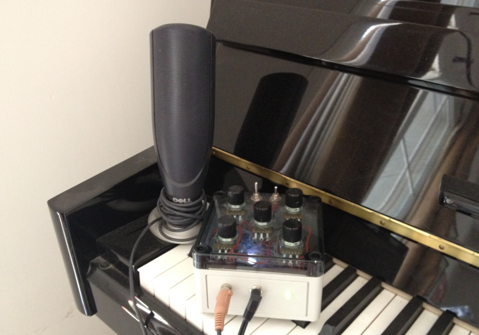
Here is mine as used in the video. For the nightclub in a box project I will be adding two amplifiers based on the previous rcarduino post - Adding Audio To Arduino Projects - http://rcarduino.blogspot.com/2012/08/adding-audio-to-arduino-projects.html


The final part of the build to to plug the Illutron B into your MP3 Player docking station - I used a section of head phone cable soldered to a three pin header for this -


The code is now available for download on the RCArduino downloads page here -

http://rcarduino.blogspot.ae/2014/02/rcarduino-downloads.html

If you have any problems with the download, contact me 'DuaneB' through the Arduino forum or leave a comment.

In a future post I will explore more of the capabilities of the Illutron B, the Illutron team will also be working on new Illutron synth based projects.

Stay tuned

Duane B


Sunday, August 19, 2012

Adding Audio to Arduino Projects

Sometimes a project just needs to be louder, whether its a synthesizer, alarm clock, autonomous robot or the RC Arduino lap timer.

In the case of the lap timer, I want people in the club house to know when a lap record has been broken, it all adds to the pressure and the fun of racing.

One incredibly simple solution to getting more sound from a micro controller is the LM386 series of amplifier chips. These can give project quality audio for less than a dollar.  They even make a passable one dollar MP3 docking station and are the basis of the 'little gem' guitar amplifier.


LM386-N4 Big Audio In A Tiny Package - 

Parts List - 
1 x LM386-N4
2 x 100uf Electrolytic Capacitors
1 x 0.1uf Capacitor
1 x 100Ohm Resistor
1 x 10K Potentiometer

Circuit pictured is used to drive a PC Speaker in the RCArduino Lap Timer project - See the video.


The LM386 Minimal Components Circuit

The datasheet for the LM386-N4 which I am using provides some example circuits but these require non standard capacitors - by non standard I really mean that most of us keep 'decade' capacitors meaning the tens - 0.01uf , 0.1uf, 1uf, 10uf, 100uf. The sample circuits require 250uf and 0.05 uf capacitors.

As I didn't have these values, I built the sample circuits with 100's in series and 0.1's in parallel to get 200uf and 0.05uf. After playing with the circuit for a while I removed the series and parallel capacitors leaving just a single 100uf and one 0.01 uf capacitor. This variation of the recommended circuit works perfectly well, and is now included in the built version of the RCArduino Lap Timer.

So for a super simple chip to add quality sound and volume to a project order a few LM386N4's its amazing how many projects can benefit from bigger sound when its as easy as this.


Simplified LM386N4 Circuit To Drive PC Speakers From A Micro controller

Caution : The new generation of 32 Bit ARM chips used by the Arduino Due are less able to sink and source current than the AVR Chips used in the 8-bit Arduinos. A number of users have reported burnt out DAC (Digital To Analog Converter) outputs while using the Arduino Due. It is suggested that a series current limiting resistor should be used between the Arduino Due DAC Outputs and external circuitry.

There are currently a number of topics covering the Arduino DAC outputs and pin protection in general on the Arduino Due forum - http://arduino.cc/forum/index.php/board,87.0.html

The circuit below shows a suitable circuit for 8-bit AVR Arduinos - UNO, Mega, Leonardo etc.


 Data sheet with alternative circuits and full application details -

http://www.ti.com/lit/ds/symlink/lm386.pdf

The RCArduino Five Dollar Synthesizer, Arduino audio played through the LM386 amplifier driving a PC Speaker

Project details here -
http://rcarduino.blogspot.com/2012/10/five-dollar-synthesiser.html


The Auduino
The five dollar synth is a great project if your up to re purposing an existing keyboard, if not, you really have to build an Auduino.

The Auduino is one of the best sounding Arduino Audio projects, it is also the easiest to build requiring only five potentiometers.
 
Update: The first video is my own Auduino, any others I post are enhanced Auduino's which for one reason of another are nicer than mine, so skip mine and have a look at what everyone else is able to get from this simple sketch through the use of clever additions -

My Own Audiuno - 
Totally standard Audiuno code with output direct to a PC Speaker using the LM386 Amplifier circuit shown in this post.


Auduino By DenkiTribe

A very musical Audiuno based jam -

The project enclosure seems to be closely related to a pizza box but we can forgive that for the very musical session. Modifications are obviously the stylus based pitch control and the addition of external echo.


Auduino By 'TheHangMansAxe'

As far as I can tell, thehangmansaxe has enhanced his auduino with two additions

1) An LED and LDR that 'gates' the output, for those of us with no audio background, gating is essentially connecting and disconnecting a signal from the output.

In DIY Projects LDRs are often used for this as they have an output which is a rough approximation to many stringed instrument where the initial note is loud but then decays away over time. LDRs initially react to light very quickly, but when the light is removed, they settle more slowly allowing the not to linger slightly.

At around the 1 minute mark the user shows the LED switching on and off through the side of the instrument.


2) Thermin style note sensing. The user does not provide any details, but I assume that the note is being controlled by infra red bouncing off the users hand. The original Audiuno design provided on tinkerkit uses five analogue inputs to control the sound, generally these are connected to puts but can also be replaced by any device capable of providing and analogue output.

UPDATE - 25/10/2012 - Added this section to explain how the Auduino works. It needs diagrams and rewritting for reduced length and increased clarity.


How does the Auduino work ?
While I am a big fan of the Auduino, its not that well documented. It is described as a 'granular synthesiser', I spent a lot of time reading up on granular synthesis and reverse engineering the code before I was able to understand exactly how the Auduino generates its particular sound.

A granular synthesizer is usually described as generating sound by rapidly repeating a small 'grain' of sound and if you read through the Auduino code you will certainly find repeated reference to grains however what and where are the grains ?

Outside of the Auduino project, the term grain is most often used to describe grains of sound which are sampled from real life speech, instruments or environmental sounds - a grain is a very short sample in the order of 1/10 to 1/10,000th of a second as opposed to the sampled vocal and drum tracks that you might be familiar with.

Pereshaped points out in the comments below that the synthesis technique used by the Auduino is closer to 'Vosim' that grain synthesis.
 
The Auduino code is actually very clever and efficient, instead of storing a grain the Auduino generates the grain in realtime using a simple counter.
The variables grainPhaseAcc and grainPhaseAcc2 are basically just counters. They count up, then down at a rate determined by grainPhaseInc and grainPhaseInc2. If you were to plot the value of these variables over time each one would give you a triangle waveform.

  // Increment the phase of the grain oscillators
  grainPhaseAcc += grainPhaseInc;
  grain2PhaseAcc += grain2PhaseInc;

The two variables grainPhaseInc and grainPhaseInc2 are directly controlled by two of the Auduino inputs. Adjust the potentiometers up and down and you will hear a frequency component of the output rise and fall in pitch as the relevant triangle wave increases and decreases in frequency.

These are not our main pitch control though, vary them up and down and while the quality of the note will change dramatically, the pitch of the note will stay the same.

The note pitch is controlled by the variable synchPhaseInc. This has an interesting job to do, it controls the rate at which yet another counter - synchPhaseAcc overflows. Whenever this counter overflows, it resets the the two triangle waveforms to an initial synchronized position. This periodic resetting of the two waveforms is what causes repetition of a repeatable 'grain' of sound. The rate of repetition gives the output its pitch.


Its actually a lot more interesting than that, what makes the Auduino sound so engaging is that as you increase or decrease the output frequency so you adjust the amount of the grain that is repeated adding additional layers of colour to the output tones.

The final stroke of genius in the Auduino design (its not my design so I am allowed to say this) is the use of the pentatonic scale. Instead of allowing you to choose any frequency you like the main pitch control is mapped to the musical scale know as the pentatonic scale. This is what gives the Auduino a kind of bluesy sound and ensures that you will never hit a duff note. For more on the pentatonic scale check out the wikipedia article.


A picture speaks a thousand works and Miro2424 has kindly posted this video of an Auduino in action on youtube. In the video you will see the two triangle waves superimposed on each other, you will see and hear how they are used to create both the pitch and the tone of the sound.


Auduino By Miro2424
I have been trying to learn how an 'addative', 'grain' or 'frequency on frequency' synthesizer like the Auduino works. This clip from Miro2424 shows the Auduino output visualised through what I am guessing is a high end PC Sound card. In the clip you can see the two triangular grains super imposed on each other and how they are used to create and vary the sound. Very happy to have found this, it makes it all easier to understand.


Everyone should have at least one Auduino, if you have a spare Arduino and 5 potentionmeters you can build one right now - http://code.google.com/p/tinkerit/wiki/Auduino

UPDATE - 01/02/2012
Here is another great variation on the Auduino by Moshang, this one also has the coolest name 'The Groovesizer' and also the best looking case of any I have seen so far.

The groovesizer extends the Auduino with a built in sixteen step sequencer.

Full details here - http://moshang.net/soundjeweler_blog/technique/groovesizer-diy-16-step-sequencer-and-synth/


UPDATE - 16/11/2012 - The Auduino is the original work of Peter Knight, the project home page appears to be inactive. RCArduino has previously reported a bug fix to the project which has not been updated. On the basis that the project is no longer active, a full version of the Auduino code including the bug fix and an added echo effect can be found on RCArduino -
http://rcarduino.blogspot.com/2012/11/auduino-with-delay.html
These two RC Arduino projects can also be built using identical hardware, upload them to your Auduino for a change of scene, you can always re upload the Auduino when your finished.

http://rcarduino.blogspot.com/2012/10/arduino-modular-synthesizer-part-one.html


Duane B

Tuesday, April 3, 2012

Servo Problems - Part 2 - A Demonstration


If you have read the post Servo Problems With Arduino you will recognise the following as an apparently working circuit for driving one or more servos -


Lets have another look at this circuit -

In the following video I have replaced the 4 AA batteries that are powering the servos with a single 9 volt PP3 Battery. This battery is providing power to the servos and two LEDs through a 7805 regulator. This is a common regulator used in many Arduino's such as the Boarduino and standalone Arduinos. It is a reasonable replica of the 9V PP3 battery and on board regulator powering my Arduino UNO in the first video.

PP3 9 Volt Battery and The 7805 Regulator (red highlight) That Power A Boarduino

I have made one change to the circuit and introduced two series LEDs (and a current limiting resistor). Like all LEDs these two require a minimum voltage to light, in this case, combined they require around 4.5 volts. Thats about the minimum operating voltage of an Arduino so lets imagine that the LEDs are infact an Arduino sharing the same power circuit as the Servos.

Now lets see what happens under load -

Servo Under Static Load

When the LEDs go out, it is because the are no longer getting their minimum 4.5 volts.

When we apply a load to the servo, it draws more current, in this case it draws more current than the battery is able to deliver, when this happens, the battery voltage drops.

If this really was your Arduino it would have 'browned out' or at the very least your project would begin to behave oddly.

In the following video the servo is being instructed to sweep, even less effort is required to get the servo to take our imaginary Arduino out of service -

Loading Servos In Motion


Something else interesting is also happening, its easier to see in the following videos, but even without a load applied the servo is able to take down the LED Arduino -

In this circuit I have added another LED in the top left corner for comparison, this LED is driven by the Arduino power circuit (+5v -> 680 Omh resistor -> GND). The other two LEDs remain on the servo power circuit, note how the Arduino LED remains at a constant brightness whereas the imaginary Arduino LEDs flash noticeably -

Three Servos Overloading The Power Circuit


The camera is not fast enough to capture the full extent of the flashing in the LEDs, but if we can see it at all , you can be sure the Arduino is feeling it.

So what is this noise, where is it coming from and what can we do about it ?

Its not really noise, its our battery telling us that it just can't deliver the current we are asking for. The video is produced with no load, applying even a light load takes the LEDs out completely - thats not noise, thats your circuit telling you something.

The flashing is in sync with the servos changing direction at the end of their sweep. I don't have the means to investigate this further but suspect its down to the following effects -

1) The servos internal motor driver will be switching one set of transistors off and another on in order to reverse the motor
2) Momentum, the servo has to stop its internal motor and gears and get them moving in the opposite direction, this will require a burst of power.

Ok, but how do we get rid of the noise ?

As its not really noise, just our circuits way of telling us it doesn't have enough power, the solution is to add power.

Repeating the tests with the original four AA Battery pack provided improved results however it was not until I powered the circuit with a high power LIPO battery that the LEDs would remain lit at a constant brightness.


More on LIPOs and other batteries in a future post and some suggestions on using a similar LED set up to 'let the hardware do the work' in monitoring the power situation.

Duane B

Wednesday, January 25, 2012

Extra Channels On The Cheap

Ever wanted to add an extra channel to your car, boat, robot ?

One of the guys commenting on the blog mentioned that he was working on a tugboat project. This brought to mind the one or two marine models that I have seen, from memory these models are very big on scale detail and moving parts.

This set me to thinking what could a micro controller do in this environment ?

Something very quickly came to mind that could be used in this application or any other where you would like to add one or two 'toggle' channels to a model. These are channels that are either on or off, and are ideal for setting off signalling sequences, turning lights on and off, switching mix modes remotely, activating a scale winch or basically any other application you can think of that requires the ability to remotely switch something between two states or positions.

This is a very simple trick which I have used to remotely toggle between dad mode and child mode in one of my projects. The trick is to use the small zone between neutral throttle and the point at which the motor overcomes stall inertia.

If neutral throttle is a pulse of 1500, you can use 1510-1525 to toggle one action and 1475 to 1490 to toggle another action. The values may need adjusting in particular applications, but the concept is the same -


If the throttle is held in this region, switch an indicator light on and take a time stamp.

If the throttle moves out of this region, switch the indicator light off and clear the time stamp.

If the throttle remains in the region, check the time stamp against the current time, if the difference exceeds your switch period, then toggle your mode/lights/winch whatever.


Its the method I use to switch modes in the child mode project, its incredibly useful to be able to switch parts of your code on and off remotely while the model is running. But the same approach applies equally well to all sorts of scale model applications such as I have suggested above.

As we are using the stall space around neutral, our model will not be moving, so there is no reason why we could not combine this with the steering channels to add even more channels.

By my calculation using throttle and steering channels gives 2 (up,down) * 3 (little left, little right, centered) = 6 on/off channels.


How much do these extra toggle channels cost ? An Arduino UNO is around 20 GBP but you can assemble your own from components for 7 GBP and the best part is the Arduino can do a lot more than just switch something on and off, any one of those six toggle channels could set off pre programmed sequences across multiple servos, lights, speakers and other actuators.

Simple Example - Toggling One Mode Using Throttle Channel

  if(nThrottleIn <= THROTTLE_THRESHOLD && nThrottleIn >= (THROTTLE_THRESHOLD-20))
   {
     unsigned long ulCurrentCounter = millis();
     if(ulModeSwitchCounter == 0)
     {
       ulModeSwitchCounter = ulCurrentCounter;
     }
     else
     {
       if((ulCurrentCounter - ulModeSwitchCounter) > MODE_SWITCH_DURATION)
       {
         
ulModeSwitchCounter = 0;
          // SWITCH YOUR MODE HERE

       }
     }
   }


Duane B.


Friday, January 20, 2012

How To Read an RC Receiver With A Microcontroller - Part 2

If you read 'How To Read an RC Receiver With A Microcontroller - Part 1' you will probably have guessed that my approach is based around interrupts, you may even be thinking 'So what, there is nothing new in any of this'.

Your right on the first part, but writing the code to take control of the throttle signal on my 40Km/h RC Race car was a very long way from reading a signal and writing it to the serial port.

What Could Possibly Go Wrong ?

The real world quickly gets in the way - underground cables, vibration, noise from the RC Components in the car, mobile phone transmitters, the built up environment, low transmitter batteries, even passing traffic effects the signal.

During the design and test of the code, I had two hardware problems with a dry solder joint on the power capacitor attached to the electronic speed controller and a track on my low quality strip board which crumbled away. At the time I was not aware that these hardware issues were the cause and so I investigated every conceivable cause of interference.


Power Capacitor Soldered to ESC Power Terminals
Strip board track repaired after crumbling away!


One simple test repeated since the hardware issues were resolved involved propping the RC Car wheels off the ground and then walking away from the car with the transmitter. I repeated this many times, increasing the distance or changing the line of sight to include/exclude features in the built up environment. I was very surprised to see just how badly the signal degrades as you move the transmitter away from the car.


Transmitter and Receiver Adjacent To Each Other

Transmitter and Receiver 20 Meters Apart.


The charts show the pulse width variation over time with the transmitter set at a constant neutral signal. A straight line would indicate there is no variation in the pulse width, this is the result we might initially expect.

The two charts are generated using the code presented in the preceding post 'How To Read an RC Receiver With A Microcontroller - Part 1'


To create the charts, the serial output was cut and paste into Microsoft Excel.

The charts clearly show that as the distance between the transmitter and receiver increases, so the variation in the signal increases. My tests have shown that the built up environment has an additional effect, further compounding the effects of distance.


With no controller input and the transmitter positioned just 20 meters away, the signal output by the receiver would randomly wander by as much as 30 milliseconds either side of the transmitter signal. Some of this would be due to the built up environment, moving the transmitter to a position occluded by a steel reinforced concrete pillar would cause chaos in the servo at only 20 meters.

So this isn't going to work is it ?

Not only does it work, but it works brilliantly. The best thing I can say about using the Arduino to control the throttle signal is that you can't tell its there.

The first few times I drove the current version of the software I kept having to bring the car back in to check that I hadn't shorted something and bypassed the Arduino completely.

So how does it work ?

First of all the mechanical nature of the servos and motors in our equipment provides a certain amount of signal smoothing, put simply, they just cannot move fast enough to react to the variation in the signal and so their position at any point in time reflects an average value of the signal in the preceding milli seconds.

Sample signal variation over 1 second - a random walk around the value 1540 - the value output by the transmitter.


In addition to the smoothing provided by the mechanical nature of the car, I have included a 'confidence' algorithm in the code. This algorithm compares the current input to the previous output, if the variation is small it ranks the new signal with a low value, if the variation is larger, the signal scores a higher degree of confidence. If the signal returns to its original value the confidence is reset to zero. The basic concept is that if we receive a vastly different signal, the chances are that its a new command from the driver, but if we receive a series of wandering signals they can generally be ignored provided that they do not creep in one direction which would indicate a subtle but valid input from the driver.


// Confidence Version 2, smaller, better, faster ?

int nDifference = nThrottleIn - nThrottleOut;

 if(nDifference == 0)
 {
    nConfidence = 0;
 }
 else
 {
   nConfidence += (nDifference/4);
 }
  
 if((nConfidence >= SENSITIVITY) || (nConfidence <= -SENSITIVITY)) // SENSITIVITY = 8
 {
   nConfidence = 0;
  
   // do something with this pulse ....
 }


I am currently open minded as to the value of the confidence algorithm. Standard RC Equipment works well enough without the addition of this algorithm, however it is at a cost of battery drain, heat and mechanical wear. The real value of the algorithm in a mircocontroller environment is potentially in providing a lightweight, easily tuned mechanism to condition the signal for input into subsequent algorithms without introducing the lag that results from smoothing across multiple samples.

The following charts show a badly degraded signal before and after the simple confidence algorithm -

Signal Before Algorithm


Signal After Algorithm


In the charts above, the confidence algorithm clearly smooths a large amount of the signal noise, however it is too sensitive to cope with the extremes.

One feature of the algorithm is that the sensitivity can be easily changed through a single variable. 

Test Conditions 
The tests were performed with the transmitter and receiver at opposite ends of a steel reinforced concrete villa  -

The line of sight was occluded by at least two walls
The receiver was adjacent to and transmitting serial data to a laptop. 
The line of sight included an LCD TV and a kitchen appliance.

The reinforced walls, LCD TV and Kitchen Appliance have all been observed to cause a large degree of interference to RC equipment and signals. 

Ideally the tests should be repeated with a higher value sensitivity however the test conditions are extreme and do not provide any qualification of the algorithms real world usefulness.

At present the algorithm has very little performance impact and clearly removes some noise, however before the algorithm can be qualified into or out of the RC Arduino projects it will need to be tested in the two most common RC Applications -

1) Racing - This is a tough environment with multiple transmitters sharing a fairly narrow physical and electro magnetic space. 
2) Street Driving - This has its own challenges in the form of distorted signals reflecting from the build up environment.

In use to date, the confidence algorithm has no detrimental effect so it stays 'in' with one small change - 'Sensitivity' actually has the opposite effect and should really be renamed 'Damping' to reflect it effect on the signal variation.

Next up - Bad Pulses And What To Do With Them

How To Read an RC Receiver With A Microcontroller - Part 1

Its a very common question, 'How do I read an RC Receiver with my micro controller' and the answer is often very simple however the simple answer is close to useless in a real world application.

The approach outlined in this series of posts has been tested in an RC Race car running at 40+ Kmh at a range of 100 meters.

The approach is reliable, resilient, easy to understand and easy to modify. It has been tested using using 27Mhz AM radio equipment and entry level electronics. Use of better quality electronics and radio equipment will provide improvements in range and signal quality however as the development process has demonstrated, even low end equipment can be interfaced with Arduino for control of an RC Race car.

Update 05/11/12 Read multiple RC channels with a smoother, faster library -
http://rcarduino.blogspot.com/2012/11/how-to-read-rc-channels-rcarduinofastlib.html
For the background to this and the original sketch before optimisation see - 
http://rcarduino.blogspot.com/2012/04/how-to-read-multiple-rc-channels-draft.html


Update 04/11/12 - For those of you looking to read a PPM Stream instead of individual channels, I will have a small fast library up this week - will post an update with the link here -
http://rcarduino.blogspot.ae/2012/11/how-to-read-rc-receiver-ppm-stream.html


Background Information

What are we looking for when we read from an RC Receiver ? Its not what I originally expected, my guess was that it was an analogue signal that would be amplified by the speed controller or servo controller to drive the motors. Its not analogue at all, its actually mostly empty space.

Each channel decoded by your receiver is sent to your ESCs and Servos as a train of pulses, these pulses are sent about 50 times a second but the suprising part is, each pulse only lasts between one and two milliseconds (1/1000 to 2/1000 of a second). Before the next pulse arrives, there is a gap of 10 times the length of the even longest pulse.

In an Electric RC Car a pulse width of 1000 is full reverse or brake, a pulse width of 2000 is full throttle and a pulse of 1500 is neutral. Note that these may be reversed, but the nature and range of the signal does not change.

This pulse train as it comes from the receiver could not be used to drive anything, not even a toy motor. The ESC or Servo control circuitry takes the pulse train as an input and generates a very different output, not just in power, but also in profile and even polarity in the case of reversing a motor.


The Simple Approach and Why Its Wrong

A common suggestion is to connect the receiver to the microcontroler such that there is a common ground (GND) between the two devices and then attach the white or orange signal wire from the receiver to one of the digital input microcontroller pins.

From here there are a variety of approaches to reading the values from the pins -

PulseIn (a blocking polling approach)

PulseIn is a function available with the Arduino that implements an approach know as 'poling'. It essentially sits around waiting for something to happen, until something happens the rest of your code is blocked. This is okay for a simple lab exercise to read and print values from a receiver but it is a hopeless approach for a real world application. Fortunately there are better approaches that do not require a major learning curve.

Timers

There is an example in the Arduino Playground which uses timers ReadReceiver. It may offer greater resolution than the method I am using, but it is also considerably more complicated and as I will show in a follow up post, the source receiver signal degrades rapidly as you move outside the lab rendering the increased accuracy less valuable.

Interrupts

The Timer example and my own approach both use Interrupts. Interrupts allow you to declare your interest in an event and then have the micro controller 'interrupt' your code whenever the event occurs.

Lets take a closer look at the channel signal and determine which bits we should be interested in -


If all we are interested in is the pulse duration, why not use pulseIn ? after all there is nothing else of interest in the signal.

The Arduino UNO is able to perform 16 million operations in one second. In the 2 milli second duration of a full throttle pulse, the Arduino could have performed 32,000 operations ! Thats a lot of wasted power. But it gets worse, what if you call pulseIn immediately after a pulse, you will have to wait a whole 20 milliseconds for the next pulse to arrive and complete. Thats a full 320,000 operations useful operations your code could have completed.

On average you can expect to call pulseIn in the center between two pulses, this means that over an extended period, half or your available processing power is wasted just waiting for the next pulse to arrive and complete. If you add more inputs, the approach becomes quickly unsustainable as you can only give your attention to a single input at a time.

Don't Use Pulse In !

Here are some updates showing the code in action - 

Active Yaw Control Of An RC Race Car
http://rcarduino.blogspot.com/2012/07/rcarduino-yaw-control-part-2.html 

Mapping RC Car Controls To A  Tank Tracked Robot
http://rcarduino.blogspot.com/2012/05/interfacing-rc-channels-to-l293d-motor.html 


Using an interrupt to efficiently detect new pulses and output to serial

For reading multiple RC Channels see - 

http://rcarduino.blogspot.co.uk/2012/04/how-to-read-multiple-rc-channels-draft.html


// First Example in a series of posts illustrating reading an RC Receiver with
// micro controller interrupts.
//
// Subsequent posts will provide enhancements required for real world operation
// in high speed applications with multiple inputs.
//
// http://rcarduino.blogspot.com/
//
// Posts in the series will be titled - How To Read an RC Receiver With A Microcontroller

// See also http://rcarduino.blogspot.co.uk/2012/04/how-to-read-multiple-rc-channels-draft.html 

#define THROTTLE_SIGNAL_IN 0 // INTERRUPT 0 = DIGITAL PIN 2 - use the interrupt number in attachInterrupt
#define THROTTLE_SIGNAL_IN_PIN 2 // INTERRUPT 0 = DIGITAL PIN 2 - use the PIN number in digitalRead

#define NEUTRAL_THROTTLE 1500 // this is the duration in microseconds of neutral throttle on an electric RC Car

volatile int nThrottleIn = NEUTRAL_THROTTLE; // volatile, we set this in the Interrupt and read it in loop so it must be declared volatile
volatile unsigned long ulStartPeriod = 0; // set in the interrupt
volatile boolean bNewThrottleSignal = false; // set in the interrupt and read in the loop
// we could use nThrottleIn = 0 in loop instead of a separate variable, but using bNewThrottleSignal to indicate we have a new signal
// is clearer for this first example

void setup()
{
  // tell the Arduino we want the function calcInput to be called whenever INT0 (digital pin 2) changes from HIGH to LOW or LOW to HIGH
  // catching these changes will allow us to calculate how long the input pulse is
  attachInterrupt(THROTTLE_SIGNAL_IN,calcInput,CHANGE);

  Serial.begin(9600);
}

void loop()
{
 // if a new throttle signal has been measured, lets print the value to serial, if not our code could carry on with some other processing
 if(bNewThrottleSignal)
 {

   Serial.println(nThrottleIn); 

   // set this back to false when we have finished
   // with nThrottleIn, while true, calcInput will not update
   // nThrottleIn
   bNewThrottleSignal = false;
 }

 // other processing ...
}

void calcInput()
{
  // if the pin is high, its the start of an interrupt
  if(digitalRead(THROTTLE_SIGNAL_IN_PIN) == HIGH)
  {
    // get the time using micros - when our code gets really busy this will become inaccurate, but for the current application its
    // easy to understand and works very well
    ulStartPeriod = micros();
  }
  else
  {
    // if the pin is low, its the falling edge of the pulse so now we can calculate the pulse duration by subtracting the
    // start time ulStartPeriod from the current time returned by micros()
    if(ulStartPeriod && (bNewThrottleSignal == false))
    {
      nThrottleIn = (int)(micros() - ulStartPeriod);
      ulStartPeriod = 0;

      // tell loop we have a new signal on the throttle channel
      // we will not update nThrottleIn until loop sets
      // bNewThrottleSignal back to false
      bNewThrottleSignal = true;
    }
  }
}


Next up - Part 2 including what does the signal really look like ? and more of the code to deal with it.

For reading multiple channels using an interrupt driven technique see -

http://rcarduino.blogspot.co.uk/2012/04/how-to-read-multiple-rc-channels-draft.html

Friday, December 30, 2011

Traction Control Part 1.2 - Taking Control

So far I have used two pairs of IR Emitter, Detector diodes to monitor the speed of the front wheels, I use this information to detect wheel spin based on the assumption that if one of the wheels is spinning more than 20% faster than the other then I have lost traction in that wheel. This is all covered in the post Traction Control Part 1.1.

The next step is to interface the Arduino between the remote control receiver that receives the signal from the users radio and the electronic speed controller that delivers power to the electric motor based on the users signal.

As the first step towards this I will implement a 'Child Mode' for my cars. The idea here is that if I hold the brake for 10 Seconds, the Arduino will enter 'child mode' and map the throttle input range to a more limited 'child' range. This way whenever my son or daughter want to have a go I can discretely hold the brake to activate child mode before passing them the transmitter, a similar signal will be used to revert to standard operation.

Prototype using Arduino to read input pulse width, then use the Servo library to generate output pulse of same width. The picture shows a servo connected rather than the electronic speed control but the pulse, logic and connectivity is the same for both. I prefer testing with a cheap servo rather than a racing motor spinning at 21,000 RPM !


I have had an early version of this working where the Arduino was capturing the throttle pulse width through an interrupt and then using the writeMicroseconds function of the Servo library to control the servo. This proved the concept of decoupling the servo from the receiver and giving the Arduino responsibility for mapping from the input signal to the servo.

During the testing of this code I found that I had a massive electrical noise problem when the Arduino was powered from the same LIPO battery as the rest of the car, this put the project on hold while I investigated strategies for dealing with the noise. I now have the noise under control and in the next few days hope to be able to post the 'Child Mode' code and confirm that the noise really is under control and the strategy used to control it.

Tuesday, December 27, 2011

Anti-yaw control Part 1

I gave a new kit its first run today, its a Tamiya Sand Scorcher which is a reissue of a 30 year old design. It looks fantastic in motion but could really use some on board electronic help to stay on track.


A little bit of history

Back when the kit was issued it would have been powered by a 7.2 volt Nicad battery which took about 18 hours to trickle charge and lasted about 7 minutes. Today I am running the reissue on an 8.4 Volt Lipo which takes an hour to charge and lasts about 30 minutes, its also about half the weight of the original batteries.

The kit itself is very different from todays plastic and carbon kits which contain very few metal parts, the sand scorcher is almost entirely metal with parts made from stainless steel, aluminium and brass. 

Its a real novelty to put together if your used to todays kits, it also makes for a more 'scale' drive as the weightier metal parts cause the car flop, lurch and bounce around far more realistically than a modern lightweight plastic kit.


I am not sure whether its the lighter, more powerful modern day battery, the rear wheel drive chassis, the desert sand or just my driving but the car is impossible to drive in a straight line. Every rear wheel drive radio controlled car I have ever driven has had this problem, but this one is the worst of the lot. One solution which many people have tried with RWD RC Cars is to put a gyroscope into the car.

A gyroscope fitted in my Tamiya M04 Rear Wheel Drive On Road Chassis.


The gyroscope senses the car beginning to fishtail and instantly steers into the skid (counter steers) to keep the car moving forward. This can also be useful over rough ground and jumps where the gyroscope will keep the front wheels pointing into the landing even if the car starts to rotate to the side in the air, this reduces the stress on landing minimising parts wear and breakage, it also keeps the speed up as the car 'digs in' less on the landing.

My F103GT RWD On Road Chassis demonstrating how to 'steer into' a skid or fishtail.

If the rear of the car is skidding left the steering is turned to the left, this is known as 'steering into the skid', this stops the car from spinning out and should allow the driver to straighten out of the skid as the rear regains grip If the car skids to the right we steer to the right, in both examples you can see how the front wheels point straight ahead as a result of 'steering into the skid' its the fact that the front wheels point in the direction of travel that should stop the car from spinning out and allow the driver to regain control.


I have had limited success using gyros, the problem is that the gyroscope is passive, it applies the same level of counter steer regardless of the cars speed and the drivers intentions, for example if I am trying to turn left, the gryoscope will sense the car rotating and tell the wheels to turn right to keep the chassis straight. This counter steering effect is adjustable through 'Gain' this is a static setting which controls how hard the gryo will try to keep the car straight. What we need for effective 'Anti Yaw or Yaw Control' is active gain that keeps out of the way when you want to turn and gets straight on the job when you don't. This is where Arduino comes in.

Project Goals - 

1) Easy to access user interface to set the base level of gain
2) Allow adjustment of the base level without needing to restart the Arduino or the Gyroscope
3) Actively adjust gain around the base level based on the signal coming from the controller
3.1) If the controller is telling the car to turn, reduce the gain so that the gyro does not fight the turn
3.2) If the controller is telling the car to accelerate or brake, increase the gain to prevent fishtail and spinout
4) Provide a simple means of turning the active components off for easy comparison between 'active anti yaw', 'passive gryo based anti yaw' and no anti yaw.
5) Provide an easy interface to set a maximum and minimum range for the servo, these limits will prevent the software/user command combination from sending signals to the servo which would cause it to exceed the mechanical limits of the model.
5.1) Record the range limits to the EEPROM for persistent storage
6) Record any operating errors to the EEPROM for persistent storage and retrieval
7) Use the project as a test bed for decoupling noise before progressing the traction control project


More soon. In the meantime, here is another picture of my fresh 'weathered' Sand Scorcher, the bodyshell is white plastic which I have painted and otherwise abused to look like 30 year old metal.


Monday, December 26, 2011

Spice Vs M-Grips


M-Grips (blue) for the win in this case. I would have expected the Spice tyres to show the highest G's but it was early morning so the spice would be struggling to get up to temperature.

Sunday, December 25, 2011

Data Logging Part 3 - Data Logged !!!

I have finally logged some data to the SD Card. To make life super easy I am logging the data is CSV format, this is a very simple text based format that can be imported by any spreadsheet application, in my case I am using Excel. The charts are simply generated by selecting the data and clicking the Excel chart icon.

The first test - Figure of 8 and Max Acceleration, Max Braking.

This first chart plots the X,Y,Z Axis as red, orange, pink. I would not have expected to see much movement in the Z axis as the car is running on reasonably flat tarmac however I am running smaller tyres than normal and so the car is dragging on the road where I haven't yet raised the suspension to compensate. Bumping along small stones is one possible cause for the movement in the Z Axis. For the remaining charts I have removed the Z - Axis so that we can see whats happening in the X and Y Axis (lateral G-Force and acceleration/braking).


I am quite pleased with the data here. For the first half of the test I was driving in a steady figure of 8, you can see this in the graph where on the left side the pink (acceleration/braking) line is steady and the lateral G-Forces swing from positive to negative as the car corners to the left and then to the right.

For the second half of the test I changed to accelerating and braking, again this shows up clearly as the pink line now moves from the positive to the negative, accelerating to braking. Interestingly you can see that the M03 is able to brake much harder that it can accelerate - pretty much what you would expect but its nice to see it captured consistently. I can also see from the red line that at the end of my acceleration and braking runs I always turned to the right to start the next run. The final point of interest is that the test strip was on a slope, and you can see this in the acceleration and braking runs where the peak G-Force under braking is higher on the first and third runs (uphill) than on the second and fourth runs (downhill).


Scatter Graph
This last graph plots each data point on an X and Y Axis, with more data it should provide a reasonable representation of the traction circle.

Again you can see that I spent more time turning left and that the brake force was about 50% higher than the acceleration.
Thats the easy bit finished. Now I need to develop a test protocol to confirm the quality of the test data. I also need to run some tests comparing spinout data with controlled high speed cornering, its pretty useless data if spinouts can't be determined from successfully negotiated high speed corners.

Thursday, December 22, 2011

Data Logging Part 2 - A User Interface

My first attempt at a micro controller user interface -
I am pretty happy with it, its a thousand times better than the horrible interfaces you get on your average Electronic Speed Controller. Take the example of a Tamiya TEU104BK, the user interface consists of a single 1*2 mm grey button hidden in a 4mm recess in the case. The button and indicator light are in highlighted area in the pic below, a 10mm push button is included for size comparison.


While I have used a great big bright red 10mm push button, I haven't completely broken away from tradition, the interface still relies on the users ability to count and interpret a sequence of flashing lights. The reason for this is that mirco controllers provide a limited number of inputs and outputs. Each of these inputs/outputs can be extremely powerful so using them up with indicators, displays and multiple push buttons is an unacceptable waste of resources.

The data logger user interface


1 Big Red 10mm Push Button
1 Bright Red LED to signal 'Recording'
1 Bright Green LED to signal 'Sending recorded data over the serial interface'

The system has 5 states -

StateMeaningRecord IndicatorSerial Indicator
IdleNot currently doing anythingBrief flash every 2 secondsAs Record
RecordRecording Data to SD CardOnOff
SerialReading SD Data and writing to serialOffOn
Memory FullNo more data can be recordedOn 1 Second/Off 1 SecondAs Record
ErrorSomething is wrongRapid Alternate with SerialRapid Alternate with Record


To move between states the push button must be held for 1 second or more. To enter record from idle 1 Second, to enter Serial from idle 4 Seconds, to exit either record or idle 1 second.

All I need now is a Micro SD Card and the data logger is up and running.