This post continues the RCArduino Lap Timer Build Along Series.
Previous steps can be found here -
Initial build along and videos -
http://rcarduino.blogspot.com/2012/07/lap-timer-build-along-part-one.html
Introduction to the timer based transponder and the required parts list -
http://rcarduino.blogspot.com/2012/08/lap-timer-build-along-part-2-transponder.html
Here are two quick demos of the system in action at the Pro RC Track in Dubai, the first shows the bread board build along lap timer and an enclosed stripboard version. The second video shows external audio enabled for lap time countdowns and fastest lap/not fastest lap indicator tones.
Transponder Overview
The transponder works by generating a simple infrared signal very similar to the one your TV Remote generates. This is an established technique which is widely used at RC Tracks, kart tracks and even automobile race tracks. If your track has an existing IR Transponder you can use the existing signal and do not need to build your own transponder. Part 4 will show you how to do this.
If you plan to build your own transponder read on.
The transponder can be powered in one of two ways -
1) Using dedicated power - If you are using the transponder in an automobile or kart, you can use a 9 Volt battery or 4 AA batteries to power the circuit directly.
2) Using buffered/shared power - The 555 Timer is a notoriously noisy component, if you intent to share power with any sensitive equipment such as an RC Receiver, you will need to buffer the shared power from the 555 timer. A cheap and effective solution is to use a 7805 voltage regulator, the final stages of this post show how to add this component.
RC Car Power
The transponder design has been extensively tested in many cars at the ProRC Track in Dubai. The transponder can easily be connected to the balance plug of a LIPO battery using a 3 pin section of PCB Header or a male balance plug if you have one. When sharing power in this way it is important to use the 7805 regulator circuit to prevent interference with the models RC Systems.
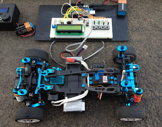
One of the test cars - The current m-chassis lap record holder at the Pro RC Track - lots of carbon, anodized aluminium and threaded oil shocks all around.
If you are not using shared power you will not need to complete the final few steps of the build (stop at step10) however if you expect to share power with any sensitive equipment at some point in the future it is worth including these steps.
How does the transponder work ?
The transponder uses the same technique and components as your TV Remote - an Infra Red light emitting diode is switched on and off 38,000 times per second, this is our carrier frequency. The carrier is generated by one of the 555 timers however in order to transmit a signal or data we need to alter the carrier in some way. The transponder uses a very simple signal - a pulse of 500 microseconds, this is generated by the second timer which simply switches the first timer on and off.
In the final part of the build series we will add the IR Detector to our Arduino circuit, the IR Detector is tuned to the 38Khz signal of the transponder. Remember we are using two timers ? One to generate the 38Khz signal and another to pulse it at 1Khz ? This provides a very simple encoding which allows us to look for pulses 500us long and know that we are receiving transponder signals rather than reflected sunlight, TV Remote signals or signals from other track side transponders.
5) Add Timing Resistors Continued
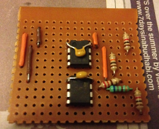 Next we need to add two more resistors to the second timer.
Connect a 220 resistor (red, red, brown) from pin 8 to pin 7 of the lower 555 timer.
Connect a 680 resistor (blue, green, brown) from pin 7 to pin 7. Yes, thats right from pin 7 to 7, its the blue resistor in the picture and for it to have any effect we need to cut the copper track beneath the resistor. Its also a good opportunity to mention that we need to cut the tracks which would otherwise connect the 555 timer pins left to right. Refer to the picture later in the post.
6.1) Add Timing Capacitors
6.2) Add Timing Connections
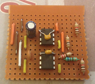
 Add the 1uf electrolytic capacitor (big black can) between pins 2 and 1 of the top 555 timer. Note that these capacitors are directional, there is a strip with a minus sign printed on it which indicates which side should connect to ground (pin 1) in the picture the strip is facing away from the camera. The other side is connected to pin 2.
Next we connect the 0.01uf ceramic capacitor between pins 1 and 2 of the lower timer. This capacitor is not directional.
Finally we need to add connections between pin 2 and 6 (trigger and threshold) of the timers. In the picture I have used yellow wire for this, it would have been possible to route the wire directly across the chips from pin 2 to 6 however in this case I have chosen to route two wires, one down from pin 6 to the empty row immediately below the chip and one back up from from the empty row to pin 2. Repeat this for each of the two timers.
7) Connect The Timers Together
 This one is easy. We want to connect the output of the first timer (top) to the enable of the second timer (bottom).
This allows the top timer which is running at 1000hz to switch the bottom timer on and off to generate our coded 38Khz signal.
This connection is shown by the white wire connecting pin 3 (output) of the top timer to pin 4 (reset) of the bottom timer.
13.1) Add The Capacitors
13.2) A Diode
13.3) Power Connection
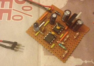 Lets do this in the order in which power enters our circuit.
1) Solder your positive power wire ( the red wire) to the very top row of the circuit, is the top left most hole.
2) Solder your ground (black wire) connection to the second row, if we have followed the steps correctly this should also be the same row as the middle pin of the 7805 regulator.
3) Connect a 0.1uf decoupling capacitor between the positive and negative power rails, in the picture you can see that I added mine to the left of the wires, you can add yours to the right as long as its immediately next to the incoming power connections.
4) Add a diode. Diodes are directional components, they only conduct electricity in the one direction, the direction is indicated by a band printed on the diode. In the picture the silver band indicates the direction in which electricity is allowed to flow. The band is facing the 7805 regulator meaning that electricity can flow into our circuit but if electricity is connected in the reverse direction the diode will prevent it from flowing and damaging our circuit.
The diode is connected to the positive power track at the top left of our circuit, once we cut the copper track underneath the diode the electricity will have to travel through the diode to reach our circuit. If we accidentally connect power in the wrong way, the diode will prevent damage to the rest of the circuit from the reverse power.
5) Add the 7805 Supporting capacitors. In order to regulate the power to our circuit, the 7805 requires some additional external components, in this case we are using two 100uf electrolytic capacitors. Like all electrolytic capacitors these are directional components, a band on the capacitor indicates the side which should be connected to ground. The middle pin of the 7805 is the ground, it should be soldered in the second track down on our board which will be the ground rail. The outer pins are the input power supply and the 5volt regulated output, each of these should be connected to the center ground pin through one of the 100uf Capacitors - make sure that the band indicating the negative side of each capacitor is connected to the center ground pin of the 7805.
Final Steps
Our final step is to cut the copper tracks under the 555 timers so that the left and right pins are not shorted together, a 3mm drill bit will do this nicely.
Final checks and trouble shooting -
1) The copper tracks on the underside of the circuit should be cut in the following locations -
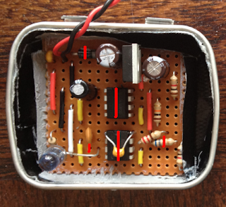 In the picture the copper tracks are running from left to right across the underneath of the board. The red marks indicate where a track should be cut, in order from top to bottom these points are -
Diode - We need to cut the track directly underneath the diode in the top left of the circuit, this will force the electricity through the diode ensuring that if we connect power the wrong way around, no electricity will flow and no damage will occur.
555 Timers - We need to cut the tracks between the left and right pins or the two timers, this means 4 cuts on the first time and four on the bottom so that the pins are not shorted by the copper tracks.
680 Ohm Resistor - This resistor is connected to pin 7 of the second (lower) 555 timer and runs horizontally along the board. As this is the same direction as the copper tracks under the board, we need to cut the track under the resistor otherwise the electricity will by pass it through the copper track.
IR LED - This component is also connected horizontally across the board. In order for the electricity to pass through the LED we need to cut the track between its two legs, in the picture the cut is marked one hole to the left of where the positive leg of the LED is soldered next to pin 3 (output) of the lower 555 timer.
2) Confirm that all of the components are correctly orientated.
3) Test the circuit - in order to test the circuit we need an IR Detector, a simple test circuit is provided in the following link, if you can light the red LED with the signal from your transponder, well done you have a working transponder.
http://learn.adafruit.com/ir-sensor/testing-an-ir-sensor
Additional References -
NE 555 Datasheet with pinout
http://www.ti.com/lit/ds/symlink/ne555.pdf
7805 Regulator Datasheet
http://www.sparkfun.com/datasheets/Components/LM7805.pdf
Next time - Adding the IR Detector to our lap timer circuit.
Bonus Step -
As an optional step you might want to consider adding the amplifier circuit shown here -
http://rcarduino.blogspot.com/2012/08/adding-audio-to-arduino-projects.html
The external audio mode can be switched on and off through the lap timer menu for extra volume when you need it. The new lap time countdown mode that you can hear in the video can also be switched on and off through the system menu.
External Audio and best lap time countdown demo -
Stay tuned ...
Duane B
Previous steps can be found here -
Initial build along and videos -
http://rcarduino.blogspot.com/2012/07/lap-timer-build-along-part-one.html
Introduction to the timer based transponder and the required parts list -
http://rcarduino.blogspot.com/2012/08/lap-timer-build-along-part-2-transponder.html
Here are two quick demos of the system in action at the Pro RC Track in Dubai, the first shows the bread board build along lap timer and an enclosed stripboard version. The second video shows external audio enabled for lap time countdowns and fastest lap/not fastest lap indicator tones.
Transponder Overview
The transponder works by generating a simple infrared signal very similar to the one your TV Remote generates. This is an established technique which is widely used at RC Tracks, kart tracks and even automobile race tracks. If your track has an existing IR Transponder you can use the existing signal and do not need to build your own transponder. Part 4 will show you how to do this.
If you plan to build your own transponder read on.
The transponder can be powered in one of two ways -
1) Using dedicated power - If you are using the transponder in an automobile or kart, you can use a 9 Volt battery or 4 AA batteries to power the circuit directly.
2) Using buffered/shared power - The 555 Timer is a notoriously noisy component, if you intent to share power with any sensitive equipment such as an RC Receiver, you will need to buffer the shared power from the 555 timer. A cheap and effective solution is to use a 7805 voltage regulator, the final stages of this post show how to add this component.
RC Car Power
The transponder design has been extensively tested in many cars at the ProRC Track in Dubai. The transponder can easily be connected to the balance plug of a LIPO battery using a 3 pin section of PCB Header or a male balance plug if you have one. When sharing power in this way it is important to use the 7805 regulator circuit to prevent interference with the models RC Systems.
One of the test cars - The current m-chassis lap record holder at the Pro RC Track - lots of carbon, anodized aluminium and threaded oil shocks all around.

If you are not using shared power you will not need to complete the final few steps of the build (stop at step10) however if you expect to share power with any sensitive equipment at some point in the future it is worth including these steps.
How does the transponder work ?
The transponder uses the same technique and components as your TV Remote - an Infra Red light emitting diode is switched on and off 38,000 times per second, this is our carrier frequency. The carrier is generated by one of the 555 timers however in order to transmit a signal or data we need to alter the carrier in some way. The transponder uses a very simple signal - a pulse of 500 microseconds, this is generated by the second timer which simply switches the first timer on and off.
In the final part of the build series we will add the IR Detector to our Arduino circuit, the IR Detector is tuned to the 38Khz signal of the transponder. Remember we are using two timers ? One to generate the 38Khz signal and another to pulse it at 1Khz ? This provides a very simple encoding which allows us to look for pulses 500us long and know that we are receiving transponder signals rather than reflected sunlight, TV Remote signals or signals from other track side transponders.
Some Alternative Transponders
The job of the transponder is to 1) Switch the diode on and off at a frequency of 38,000 times a second. 2) To enable and disable 1) At a frequency of 1,000 times a second.
In order to do this we use two connected 555 timers, the first generates the 38Khz signal and the second one enables and disables this signal at the much lower frequency of 1Khz.
The transponder circuit can be replaced with any simple circuit capable of generating two fixed frequency square waves.
Options include microcontrollers, NAND oscillators, op-amp oscillators - anything that can generate a squarewave.
Building The 555 Timer Transponder - Before and After
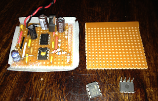 The transponder can be built on a piece of strip board 16 holes wide by 14 deep. To make sure that this is the final size of you board, remember that the rows and columns you cut will be unusable, you need 16*14 inside the cut area.
The copper strips should be running from left to right across your board - this is the orientation used throughout the build.
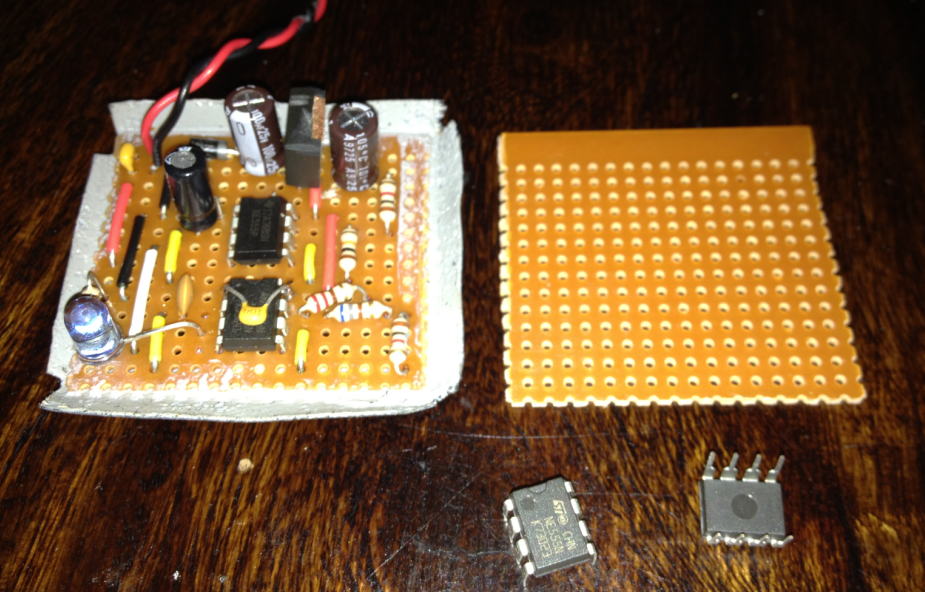
The copper strips should be running from left to right across your board - this is the orientation used throughout the build.
The Schematic
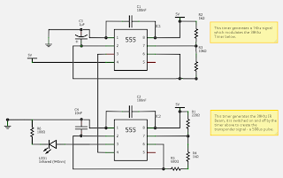 The circuit is reasonably simple with only 11 components required for pit wall use and an additional four if you plan to use the circuit in an RC vehicle.
Due to the angle in some of the pictures, its useful to double check your component placement against the schematic, also have a look at pictures from later stages for a cross reference.

Due to the angle in some of the pictures, its useful to double check your component placement against the schematic, also have a look at pictures from later stages for a cross reference.
1) Placing The 555 Timers
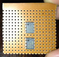 Place the two timers with the notch facing the top of your circuit. Leave four rows of space above the top timer, one row between the top and the bottom and you should be left with one more empty row below the second timer.
The timers should be placed with six free columns on either side. See the picture for reference.
Important: The copper tracks on your strip board should be running from left to right confirm this before soldering.
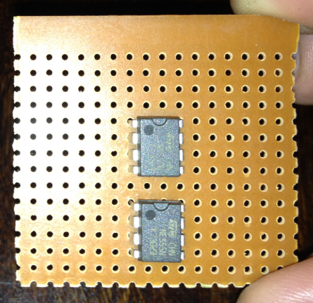
The timers should be placed with six free columns on either side. See the picture for reference.
Important: The copper tracks on your strip board should be running from left to right confirm this before soldering.
2) Add Decoupling Capacitors
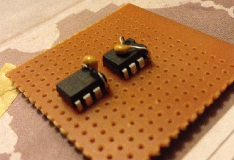
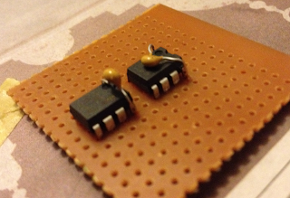 Add a 0.1uf ceramic capacitor as a decoupling capacitor across pins 1 and 8 (top left and top right) of each 555 Timer. I have soldered mine directly to pins 1 and 8 to save space.
3) Add Positive Power
 Add the connections to positive power.
When we add the 7805 regulator in a later step, the third row (counting from the top) will be our 5 volt power supply rail. Connect this to PIN 8 (top right) of both 555 Timers.
In this case I am using orange wire for the connections to the 5 volt power rail.
At this point we can also connect PIN 4 (bottom right) of the top 555 Timer to 5 volts. This is the reset pin, it is active low, so by connecting it to +5volts we ensure that the timer is never reset.
When we add the 7805 regulator in a later step, the third row (counting from the top) will be our 5 volt power supply rail. Connect this to PIN 8 (top right) of both 555 Timers.
In this case I am using orange wire for the connections to the 5 volt power rail.
At this point we can also connect PIN 4 (bottom right) of the top 555 Timer to 5 volts. This is the reset pin, it is active low, so by connecting it to +5volts we ensure that the timer is never reset.
4.1) Add Ground Connections
4.2) Add Timing Resistors
 Two steps in one here -
1) Add ground connections. Pin 1 (top left) of each 555 timer needs to be connected to the ground power rail. When we add the 7805 regulator, the second row (counting from the top) will be ground, connect this row to Pin 1 of each timer, I have used brown wire for this connection in the picture.
2) Timing resistors -
Now we add the first of our timing components. In order from top to bottom we add a 1K resistor (brown,black,red) from the 5volt power rail (third row down) to pin 7 of the top 555 Timer. Next we add a 10K resistor (brown, black, orange) from the same pin 7 to the row which we left free between the two 555 timers. The final resistor is a 1K (brown, black, red) resistor connected from pin 7 of the bottom 555 timer to the very bottom row of our board.
4.2) Add Timing Resistors

1) Add ground connections. Pin 1 (top left) of each 555 timer needs to be connected to the ground power rail. When we add the 7805 regulator, the second row (counting from the top) will be ground, connect this row to Pin 1 of each timer, I have used brown wire for this connection in the picture.
2) Timing resistors -
Now we add the first of our timing components. In order from top to bottom we add a 1K resistor (brown,black,red) from the 5volt power rail (third row down) to pin 7 of the top 555 Timer. Next we add a 10K resistor (brown, black, orange) from the same pin 7 to the row which we left free between the two 555 timers. The final resistor is a 1K (brown, black, red) resistor connected from pin 7 of the bottom 555 timer to the very bottom row of our board.
5) Add Timing Resistors Continued
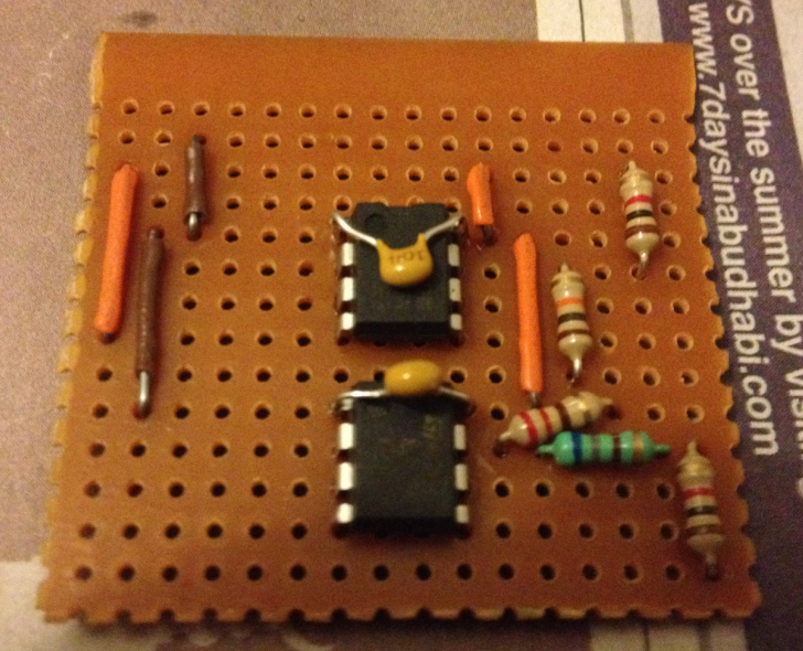
Connect a 220 resistor (red, red, brown) from pin 8 to pin 7 of the lower 555 timer.
Connect a 680 resistor (blue, green, brown) from pin 7 to pin 7. Yes, thats right from pin 7 to 7, its the blue resistor in the picture and for it to have any effect we need to cut the copper track beneath the resistor. Its also a good opportunity to mention that we need to cut the tracks which would otherwise connect the 555 timer pins left to right. Refer to the picture later in the post.
6.1) Add Timing Capacitors
6.2) Add Timing Connections

Next we connect the 0.01uf ceramic capacitor between pins 1 and 2 of the lower timer. This capacitor is not directional.
Finally we need to add connections between pin 2 and 6 (trigger and threshold) of the timers. In the picture I have used yellow wire for this, it would have been possible to route the wire directly across the chips from pin 2 to 6 however in this case I have chosen to route two wires, one down from pin 6 to the empty row immediately below the chip and one back up from from the empty row to pin 2. Repeat this for each of the two timers.
Electrolytic Capacitor Orientation
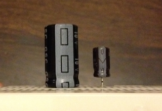 Larger value capacitors tend to be available as electrolytic capacitors, these have an appearance something like a can. Electrolytic capacitors are directional, to ensure that they are correctly placed, the cans have a band marked with a minus sign to indicate the side/pin which should be connected to ground.

7) Connect The Timers Together
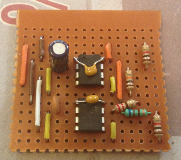
This allows the top timer which is running at 1000hz to switch the bottom timer on and off to generate our coded 38Khz signal.
This connection is shown by the white wire connecting pin 3 (output) of the top timer to pin 4 (reset) of the bottom timer.
8) LED Current Limiting Resistor
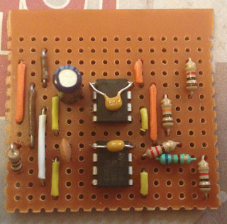 As with any LED we need to limit the current passing through our infra red LED. As we are pulsing the LED it is only on for very short durations and so we have the option of passing more current through it. In this case I am using a 100 Ohm resistor (brown, black, brown) to limit the current to 50 milli amps, you could use a lower resistor for more power which would give a greater lap detection distance however on a narrow RC Track which loops back on itself a 100 Ohm resistor is perfect.
The 100 Ohm resistor is connected from pin 3 (output) of the lower 555 timer to pin 1 (ground). In the next step we will add the LED and cut the track between pin 3 and the resistor.
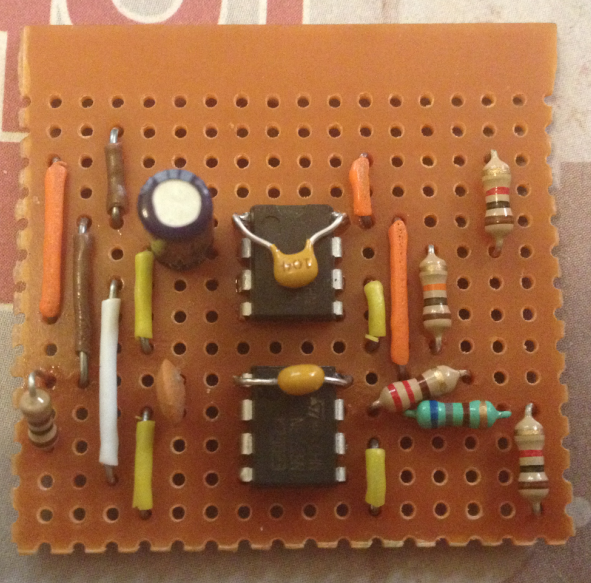
The 100 Ohm resistor is connected from pin 3 (output) of the lower 555 timer to pin 1 (ground). In the next step we will add the LED and cut the track between pin 3 and the resistor.
9) Double Check
Its a good time to double check progress. Here is the circuit constructed so far shown from the left side, double check yours against this and the previous images.

Its a good time to double check progress. Here is the circuit constructed so far shown from the left side, double check yours against this and the previous images.

10) Add The IR LED
 Not a great picture, but its an easy step.
Like all LEDs, the infra red ones are directional. This means the LED will only light if connected the correct way. As we cannot see infra red, its worth a little extra explanation to make sure we get this part right.
Most LEDs have on leg which is longer than the other, the long one should be connected to the positive (closest to the chip) and the short to negative (the path to ground is provided by the 100 Ohm resistor). However I have recently bought a batch of LEDs where the legs were cut incorrectly. To double check you LED placement, look at the inside of the LED you should see to metal plates which are roughly triangular. The smaller of the two plates is the positive side of the LED and should be connected nearest to pin 3 of the bottom timer. The other leg should be connect next to the 100 Ohm resistor where it joins the same row as pin 3. You will need to leave at least one spare hole in the board between the LED legs, you will need to bend one of the legs into an S/Z shape to do this.
As both ends of the LED are connected through the strip of copper running from the resistor to pin 3, we need to cut the copper strip to force the electricity to pass through the LED. Cut the track in the spare hole you left between the two LED Legs - refer to the underside picture for reference.

Like all LEDs, the infra red ones are directional. This means the LED will only light if connected the correct way. As we cannot see infra red, its worth a little extra explanation to make sure we get this part right.
Most LEDs have on leg which is longer than the other, the long one should be connected to the positive (closest to the chip) and the short to negative (the path to ground is provided by the 100 Ohm resistor). However I have recently bought a batch of LEDs where the legs were cut incorrectly. To double check you LED placement, look at the inside of the LED you should see to metal plates which are roughly triangular. The smaller of the two plates is the positive side of the LED and should be connected nearest to pin 3 of the bottom timer. The other leg should be connect next to the 100 Ohm resistor where it joins the same row as pin 3. You will need to leave at least one spare hole in the board between the LED legs, you will need to bend one of the legs into an S/Z shape to do this.
As both ends of the LED are connected through the strip of copper running from the resistor to pin 3, we need to cut the copper strip to force the electricity to pass through the LED. Cut the track in the spare hole you left between the two LED Legs - refer to the underside picture for reference.
Almost Finished !
The original transponder design is finished here and if you intend to use the transponder for motor racing or kart racing, just add a positive power connection to row 3 (third row down counting from the top and linked to the orange positive power wires) and a ground connection to row 2 (second row down connected to the brown ground wires).
Add a 9 volt battery or even better 4 AA Batteries and go racing !
If you intend to use the transponder in an RC Vehicle and want to share the RC Power you will need to buffer your RC Receiver from the switching noise generated by the 555 timer. The most effective way I have found to do this is by using a 7805 regulator.
The original transponder design is finished here and if you intend to use the transponder for motor racing or kart racing, just add a positive power connection to row 3 (third row down counting from the top and linked to the orange positive power wires) and a ground connection to row 2 (second row down connected to the brown ground wires).
Add a 9 volt battery or even better 4 AA Batteries and go racing !
If you intend to use the transponder in an RC Vehicle and want to share the RC Power you will need to buffer your RC Receiver from the switching noise generated by the 555 timer. The most effective way I have found to do this is by using a 7805 regulator.
11) Adding The Regulator
 The 7805 regulator prevents the switching noise in the transponder circuit from being transmitted through the power circuit and into your RC Receiver.
For the regulator to function it also needs two capacitors as supporting components which we will add in a later step.
For now place the 7805 regulator in the 10th hole counting from left to right. The regulator should be orientated so that the heat sink is on the right side of the circuit and the legs point down towards the 555 timers.
You might want to cut the heat sink off the 555 timer, this makes it easier to mount in your cars window, do this before soldering so that you do not damage the circuit while cutting.
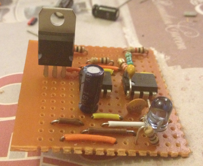
For the regulator to function it also needs two capacitors as supporting components which we will add in a later step.
For now place the 7805 regulator in the 10th hole counting from left to right. The regulator should be orientated so that the heat sink is on the right side of the circuit and the legs point down towards the 555 timers.
You might want to cut the heat sink off the 555 timer, this makes it easier to mount in your cars window, do this before soldering so that you do not damage the circuit while cutting.
13.1) Add The Capacitors
13.2) A Diode
13.3) Power Connection
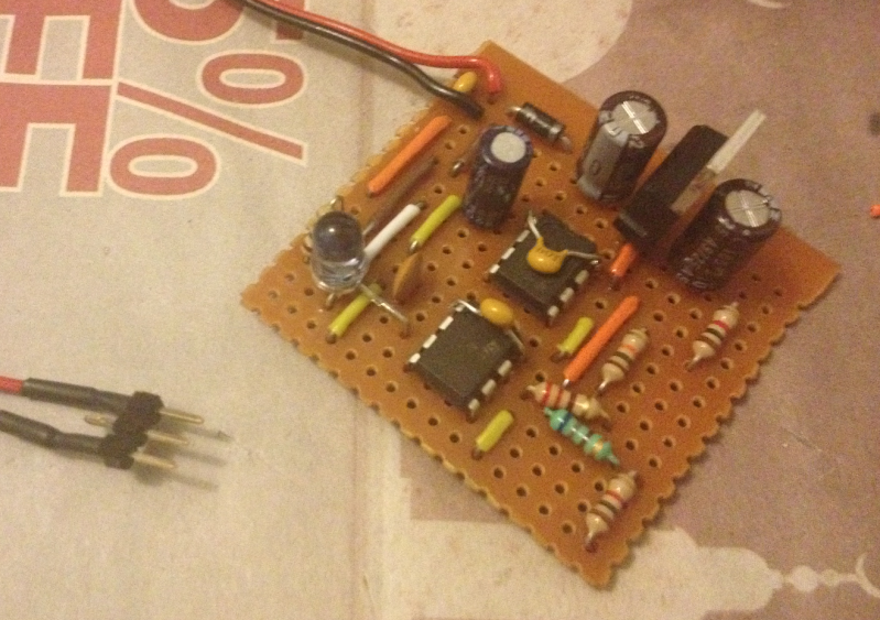
1) Solder your positive power wire ( the red wire) to the very top row of the circuit, is the top left most hole.
2) Solder your ground (black wire) connection to the second row, if we have followed the steps correctly this should also be the same row as the middle pin of the 7805 regulator.
3) Connect a 0.1uf decoupling capacitor between the positive and negative power rails, in the picture you can see that I added mine to the left of the wires, you can add yours to the right as long as its immediately next to the incoming power connections.
4) Add a diode. Diodes are directional components, they only conduct electricity in the one direction, the direction is indicated by a band printed on the diode. In the picture the silver band indicates the direction in which electricity is allowed to flow. The band is facing the 7805 regulator meaning that electricity can flow into our circuit but if electricity is connected in the reverse direction the diode will prevent it from flowing and damaging our circuit.
The diode is connected to the positive power track at the top left of our circuit, once we cut the copper track underneath the diode the electricity will have to travel through the diode to reach our circuit. If we accidentally connect power in the wrong way, the diode will prevent damage to the rest of the circuit from the reverse power.
5) Add the 7805 Supporting capacitors. In order to regulate the power to our circuit, the 7805 requires some additional external components, in this case we are using two 100uf electrolytic capacitors. Like all electrolytic capacitors these are directional components, a band on the capacitor indicates the side which should be connected to ground. The middle pin of the 7805 is the ground, it should be soldered in the second track down on our board which will be the ground rail. The outer pins are the input power supply and the 5volt regulated output, each of these should be connected to the center ground pin through one of the 100uf Capacitors - make sure that the band indicating the negative side of each capacitor is connected to the center ground pin of the 7805.
Final Steps
Our final step is to cut the copper tracks under the 555 timers so that the left and right pins are not shorted together, a 3mm drill bit will do this nicely.
Final checks and trouble shooting -
1) The copper tracks on the underside of the circuit should be cut in the following locations -
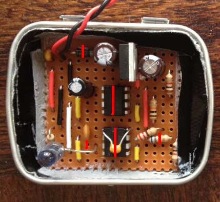
Diode - We need to cut the track directly underneath the diode in the top left of the circuit, this will force the electricity through the diode ensuring that if we connect power the wrong way around, no electricity will flow and no damage will occur.
555 Timers - We need to cut the tracks between the left and right pins or the two timers, this means 4 cuts on the first time and four on the bottom so that the pins are not shorted by the copper tracks.
680 Ohm Resistor - This resistor is connected to pin 7 of the second (lower) 555 timer and runs horizontally along the board. As this is the same direction as the copper tracks under the board, we need to cut the track under the resistor otherwise the electricity will by pass it through the copper track.
IR LED - This component is also connected horizontally across the board. In order for the electricity to pass through the LED we need to cut the track between its two legs, in the picture the cut is marked one hole to the left of where the positive leg of the LED is soldered next to pin 3 (output) of the lower 555 timer.
2) Confirm that all of the components are correctly orientated.
3) Test the circuit - in order to test the circuit we need an IR Detector, a simple test circuit is provided in the following link, if you can light the red LED with the signal from your transponder, well done you have a working transponder.
http://learn.adafruit.com/ir-sensor/testing-an-ir-sensor
Additional References -
NE 555 Datasheet with pinout
http://www.ti.com/lit/ds/symlink/ne555.pdf
7805 Regulator Datasheet
http://www.sparkfun.com/datasheets/Components/LM7805.pdf
Next time - Adding the IR Detector to our lap timer circuit.
Bonus Step -
As an optional step you might want to consider adding the amplifier circuit shown here -
http://rcarduino.blogspot.com/2012/08/adding-audio-to-arduino-projects.html
The external audio mode can be switched on and off through the lap timer menu for extra volume when you need it. The new lap time countdown mode that you can hear in the video can also be switched on and off through the system menu.
External Audio and best lap time countdown demo -
Stay tuned ...
Duane B


