 |
In the case of the lap timer, I want people in the club house to know when a lap record has been broken, it all adds to the pressure and the fun of racing.
One incredibly simple solution to getting more sound from a micro controller is the LM386 series of amplifier chips. These can give project quality audio for less than a dollar. They even make a passable one dollar MP3 docking station and are the basis of the 'little gem' guitar amplifier.
LM386-N4 Big Audio In A Tiny Package -

1 x LM386-N4
2 x 100uf Electrolytic Capacitors
1 x 0.1uf Capacitor
1 x 100Ohm Resistor
1 x 10K Potentiometer
Circuit pictured is used to drive a PC Speaker in the RCArduino Lap Timer project - See the video.
The LM386 Minimal Components Circuit
The datasheet for the LM386-N4 which I am using provides some example circuits but these require non standard capacitors - by non standard I really mean that most of us keep 'decade' capacitors meaning the tens - 0.01uf , 0.1uf, 1uf, 10uf, 100uf. The sample circuits require 250uf and 0.05 uf capacitors.
As I didn't have these values, I built the sample circuits with 100's in series and 0.1's in parallel to get 200uf and 0.05uf. After playing with the circuit for a while I removed the series and parallel capacitors leaving just a single 100uf and one 0.01 uf capacitor. This variation of the recommended circuit works perfectly well, and is now included in the built version of the RCArduino Lap Timer.
So for a super simple chip to add quality sound and volume to a project order a few LM386N4's its amazing how many projects can benefit from bigger sound when its as easy as this.
Simplified LM386N4 Circuit To Drive PC Speakers From A Micro controller
Caution : The new generation of 32 Bit ARM chips used by the Arduino Due are less able to sink and source current than the AVR Chips used in the 8-bit Arduinos. A number of users have reported burnt out DAC (Digital To Analog Converter) outputs while using the Arduino Due. It is suggested that a series current limiting resistor should be used between the Arduino Due DAC Outputs and external circuitry.
There are currently a number of topics covering the Arduino DAC outputs and pin protection in general on the Arduino Due forum - http://arduino.cc/forum/index.php/board,87.0.html
The circuit below shows a suitable circuit for 8-bit AVR Arduinos - UNO, Mega, Leonardo etc.

Data sheet with alternative circuits and full application details -
http://www.ti.com/lit/ds/symlink/lm386.pdf
The RCArduino Five Dollar Synthesizer, Arduino audio played through the LM386 amplifier driving a PC Speaker
Project details here -
http://rcarduino.blogspot.com/2012/10/five-dollar-synthesiser.html
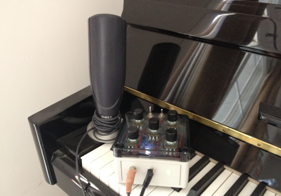
The Auduino
The five dollar synth is a great project if your up to re purposing an existing keyboard, if not, you really have to build an Auduino.
The Auduino is one of the best sounding Arduino Audio projects, it is also the easiest to build requiring only five potentiometers.
Update: The first video is my own Auduino, any others I post are enhanced Auduino's which for one reason of another are nicer than mine, so skip mine and have a look at what everyone else is able to get from this simple sketch through the use of clever additions -
My Own Audiuno -
Totally standard Audiuno code with output direct to a PC Speaker using the LM386 Amplifier circuit shown in this post.
Auduino By DenkiTribe
A very musical Audiuno based jam -
The project enclosure seems to be closely related to a pizza box but we can forgive that for the very musical session. Modifications are obviously the stylus based pitch control and the addition of external echo.
Auduino By 'TheHangMansAxe'
As far as I can tell, thehangmansaxe has enhanced his auduino with two additions
1) An LED and LDR that 'gates' the output, for those of us with no audio background, gating is essentially connecting and disconnecting a signal from the output.
In DIY Projects LDRs are often used for this as they have an output which is a rough approximation to many stringed instrument where the initial note is loud but then decays away over time. LDRs initially react to light very quickly, but when the light is removed, they settle more slowly allowing the not to linger slightly.
At around the 1 minute mark the user shows the LED switching on and off through the side of the instrument.
2) Thermin style note sensing. The user does not provide any details, but I assume that the note is being controlled by infra red bouncing off the users hand. The original Audiuno design provided on tinkerkit uses five analogue inputs to control the sound, generally these are connected to puts but can also be replaced by any device capable of providing and analogue output.
UPDATE - 25/10/2012 - Added this section to explain how the Auduino works. It needs diagrams and rewritting for reduced length and increased clarity.
How does the Auduino work ?
While I am a big fan of the Auduino, its not that well documented. It is described as a 'granular synthesiser', I spent a lot of time reading up on granular synthesis and reverse engineering the code before I was able to understand exactly how the Auduino generates its particular sound.
A granular synthesizer is usually described as generating sound by rapidly repeating a small 'grain' of sound and if you read through the Auduino code you will certainly find repeated reference to grains however what and where are the grains ?
Outside of the Auduino project, the term grain is most often used to describe grains of sound which are sampled from real life speech, instruments or environmental sounds - a grain is a very short sample in the order of 1/10 to 1/10,000th of a second as opposed to the sampled vocal and drum tracks that you might be familiar with.
Pereshaped points out in the comments below that the synthesis technique used by the Auduino is closer to 'Vosim' that grain synthesis.
The Auduino code is actually very clever and efficient, instead of storing a grain the Auduino generates the grain in realtime using a simple counter.
The variables grainPhaseAcc and grainPhaseAcc2 are basically just counters. They count up, then down at a rate determined by grainPhaseInc and grainPhaseInc2. If you were to plot the value of these variables over time each one would give you a triangle waveform.
// Increment the phase of the grain oscillators
grainPhaseAcc += grainPhaseInc;
grain2PhaseAcc += grain2PhaseInc;
The two variables grainPhaseInc and grainPhaseInc2 are directly controlled by two of the Auduino inputs. Adjust the potentiometers up and down and you will hear a frequency component of the output rise and fall in pitch as the relevant triangle wave increases and decreases in frequency.
These are not our main pitch control though, vary them up and down and while the quality of the note will change dramatically, the pitch of the note will stay the same.
The note pitch is controlled by the variable synchPhaseInc. This has an interesting job to do, it controls the rate at which yet another counter - synchPhaseAcc overflows. Whenever this counter overflows, it resets the the two triangle waveforms to an initial synchronized position. This periodic resetting of the two waveforms is what causes repetition of a repeatable 'grain' of sound. The rate of repetition gives the output its pitch.
Its actually a lot more interesting than that, what makes the Auduino sound so engaging is that as you increase or decrease the output frequency so you adjust the amount of the grain that is repeated adding additional layers of colour to the output tones.
The final stroke of genius in the Auduino design (its not my design so I am allowed to say this) is the use of the pentatonic scale. Instead of allowing you to choose any frequency you like the main pitch control is mapped to the musical scale know as the pentatonic scale. This is what gives the Auduino a kind of bluesy sound and ensures that you will never hit a duff note. For more on the pentatonic scale check out the wikipedia article.
A picture speaks a thousand works and Miro2424 has kindly posted this video of an Auduino in action on youtube. In the video you will see the two triangle waves superimposed on each other, you will see and hear how they are used to create both the pitch and the tone of the sound.
Auduino By Miro2424
I have been trying to learn how an 'addative', 'grain' or 'frequency on frequency' synthesizer like the Auduino works. This clip from Miro2424 shows the Auduino output visualised through what I am guessing is a high end PC Sound card. In the clip you can see the two triangular grains super imposed on each other and how they are used to create and vary the sound. Very happy to have found this, it makes it all easier to understand.
Everyone should have at least one Auduino, if you have a spare Arduino and 5 potentionmeters you can build one right now - http://code.google.com/p/tinkerit/wiki/Auduino
UPDATE - 01/02/2012
Here is another great variation on the Auduino by Moshang, this one also has the coolest name 'The Groovesizer' and also the best looking case of any I have seen so far.
The groovesizer extends the Auduino with a built in sixteen step sequencer.
Full details here - http://moshang.net/soundjeweler_blog/technique/groovesizer-diy-16-step-sequencer-and-synth/
UPDATE - 16/11/2012 - The Auduino is the original work of Peter Knight, the project home page appears to be inactive. RCArduino has previously reported a bug fix to the project which has not been updated. On the basis that the project is no longer active, a full version of the Auduino code including the bug fix and an added echo effect can be found on RCArduino -
http://rcarduino.blogspot.com/2012/11/auduino-with-delay.html
These two RC Arduino projects can also be built using identical hardware, upload them to your Auduino for a change of scene, you can always re upload the Auduino when your finished.
http://rcarduino.blogspot.com/2012/10/arduino-modular-synthesizer-part-one.html
Duane B
Hello.
ReplyDeleteThanks for sharing your knowledge.
There's a thing I don't understand: LM386 datasheet says that input voltage is +/-0.4V. But in your diagram you put a pot connected directly to a digital output of Arduino board (which sources 5V). Won't the LM386 be fried?
Thanks!!!
Rcarduino: Adding Audio To Arduino Projects >>>>> Download Now
Delete>>>>> Download Full
Rcarduino: Adding Audio To Arduino Projects >>>>> Download LINK
>>>>> Download Now
Rcarduino: Adding Audio To Arduino Projects >>>>> Download Full
>>>>> Download LINK ea
DeleteReally Work Fast,******************
Fast and reliable solution for Herpes Cure
I was cured from Herpes with herbal med..
Contact him for Relationship/marital problem,
He will give you the best..
Thanks to [[[robinsonbucler @ gmail com]]]
Hi,
ReplyDeleteIn this case the potentiometer is acting as a simple voltage divider. If I set the voltage divider at the low end, most of the output voltage is being dropped by the potentiometer with only a smaller amount being routed out to the LM386.
In one of my current projects I use the pot as an overdrive control, if I turn the pot up to send too much voltage into the LM386 it clips the waveform giving a harsh distorted sound which works nicely as an optional effect in audio projects.
Overdriving the chip might shorten its life over the long term, but they are pretty tough in the medium term and by using the pot as a voltage divider you have the option of turning it down so that the chip is never over driven - the key thing is that the pot gives you the option to tune this in or out as you need.
Duane B.
Oh, thanks a lot for this so fast answer!!
ReplyDeleteWhat you say it's full of sense, but there's only one more thing that annoyies me...
If LM386 accepts so low values of input voltage (+/-0.4V) and has a (minimum) gain of 20, the ouput voltage will be 0.4x20= 5V, which is the output voltage of an Arduino pin. So, which usefulness would the LM386 have in this case?
Many thanks!!
Volts are only half the story, the LM386-N4 is a one watt amplifier so at 5 volts it can deliver 200ma, thats five times more power than an Arduino pin.
ReplyDeleteIt also acts as a buffer, if you connected an Arduino pin directly to an 8ohm speaker it would try to deliver 625ma which as you know is 15 times more than the maximum a pin can safely deliver.
The amplifier provides power for the speaker and protection for the Arduino.
Duane B
Oh, thanks a lot for your explanation!! Thanks!
ReplyDeleteJust for info what you are describing in the project is more "particle" formant synthesis rather than granular. In fact it is quite similar to VoSim. It is still a microsund technique and very nice indeed. Great project and thanks for sharing.
ReplyDeleteHi, thanks for the comments, the project was originally built by a gentleman by the name of Peter Knight who described it as a granular synth. I am very much a novice in these things but it does seem that there is overlap between the different techniques. I have had some interesting sounds from a monophonic synth with variable arpeggio rates, at very high rates the notes blend into a composite waveform, I will be updating this post with details of the project - http://rcarduino.blogspot.com/2012/10/five-dollar-synthesiser.html although the blending of notes is not the main focus.
ReplyDeleteDuane B
Hey there Duane,
ReplyDeleteThanks again for the great info here. I built the LM386 output circuit according to the schematic above and got it working right away (actually, my local only had the JRC386D, but same thing apparently). Just a question regarding the "seperate power" bit. I cheated and took 5v for the amp off the arduino board and it seems to work fine, but I guess there's a reason why seperate power is advised. I want to add the amp to a hackduino based pcb I'm designing for myself to play around with. I'm feeding the hackduino with a 5v 7805-based power supply. Would it be OK to feed the 386 directly from the 9v power brick that feeds the 7805 power supply (the 386 should be OK with 9v), or would it be best to have a second 7805 on the board to feed the amp?
Hi,
ReplyDeleteThe more powerful LM386 variants can draw a lot of current, so its better not to have them sharing the 5v power rail with the Arduino. You can connect them directly to the 9v input and should get a little more volume as a result. If you find that you get noise in the amp circuit from the 9v circuit you can try adding more decoupling capacitors or as you suggest another 7805 which is possibly overkill but will provide an effective,low cost and simple buffer against power source noise - I have used them as buffers in some RC Car circuits where motor noise was a problem.
Duane B
Got it - thanks for the reply!
ReplyDeleteI need to Genarate the 1KHZ and 10KHZ sine waves using arduino. can anyone help??
ReplyDeleteIf you can find an archive of this link it will tell you all you need to know -
ReplyDeletehttp://interface.khm.de/index.php/lab/experiments/arduino-dds-sinewave-generator/
If that fails search for DDS or Arduino DDS, the technique you want is call Direct Digital Synthesis = DDS
Duane B
I'm using Arduino due board. i checked your //RCArduino Arduino Due DDS - Part 1 - Sinewaves and Fixed Point Maths-IMPORTENT.html link. can i edit that code to get the 1Khz sine wave>>
ReplyDeleteregards
Sudheera
Yes but post your questions in the comments section of the link you are asking about, rather than in this post.
DeleteDuane B
Can you please tell me which lines should I edit to get an 1khz wave. i'm doing a project for OFDM power line communication using arduino due(DAC -output pin). I did not get the whole idea in that code.
ReplyDeletethe Link is given below
http://rcarduino.blogspot.com/2012/12/arduino-due-dds-part-1-sinewaves-and.html
As above yes, but ask your questions on the link your talking about and copying in your question
DeleteDuane B
Hello May I ask a question?
ReplyDeletefor my project , Is it possible that the input of amplifier is contain 220 volt ac and the output of it is 3 volt using multitester, can you help for the schematic diagram,, can you help for what is the best thing i can do with my project?
thanks send me an email :))
Hi, Please don't take anything that you see or read on this blog and apply 220 volt ac to it. I am not qualified to work with 220 volt ac, nothing on this blog is remotely suitable to be around 220 volt ac. Sorry I cant help
DeleteDuane B
First off, thank you for the great article. I was wondering about your statement that you put the capacitors in series to double them and in parallel to halve them. It should be the other way around. Capacitance is 1/(1/C1) + (1/C2) + ... (1/Cn) when in series and C1 + C2 + ... Cn when in parallel. You can derive this by using equivalent circuits and substituting Q/V for C and applying KVL. I just wanted to point that out since you may not be getting the values you expect.
ReplyDeleteThanks, will update the post when I have 5 mins,
DeleteDuane B
Do you know what is instrumentation amplifier?
ReplyDeletemodern digital amplifier
I am all time fond of reading the blog, when I reached to this blog I wondered to read such informative article, it inspired me a lot thanks. http://inovah.net/best-6-5-car-speakers/
ReplyDeleteThis comment has been removed by the author.
ReplyDeleteHello! I'm trying to do the same but with a LM386N-1, I'm a little confused though. So the Arduino outputs a PWM 0-5V signal. The datasheet says the LM386 inputs are ground referenced. How is the chip still working, as the signal will always have a DC offset.
ReplyDeleteI always enjoy reading your blogs and how you stay positive when others may be down. Keep on fighting the good fight! Wishing you well.
ReplyDeleteI added it to my favorites blog site list and will be checking back soon.
ReplyDeletesee here
Thanks for this article.Btw here is one coolr resource which I often uses for my music projects.
ReplyDeletehttps://www.lucidsamples.com
Car Speakers in Delhi We offer auto sound, auto sound embellishments, shopper hardware, hoverboards, marine sound from brands as Kenwood, Pioneer, Soundstream, ...
ReplyDeleteA huge thanks to you for sharing this Blog your blog content is very nice ,I have read your blog your blog information is very useful.
ReplyDeleteCar Speakers in India
Great blog, Thanks For Sharing very useful information. Car Stereo in Delhi We Can Fit offer mobile car audio installation and fit all aspects of in car entertainment equipment, sat navs and parking sensors - nationwide mobile service.
ReplyDeleteThis post was reall hepful. But i need some detailed tutorial which will show me the way to build a laser security system using arduino.
ReplyDeleteHow cool was that having a full Car diversion System best 6x9 speakers without amp Through this I really makes the most of my ride each time uniquely while out and about with a few companions. So amazing!
ReplyDeleteHow cool was that having a full Car diversion System 6x9 speakers with good bass Through this I really makes the most of my ride each time uniquely while out and about with a few companions. So amazing!
ReplyDeleteThanks for the valuable information and hope that you would like this too 5.1 speakers
ReplyDeleteYou know your projects stand out of the herd. There is something special about them. It seems to me all of them are really brilliant! Hikvision Acusense
ReplyDeleteRcarduino: Adding Audio To Arduino Projects >>>>> Download Now
ReplyDelete>>>>> Download Full
Rcarduino: Adding Audio To Arduino Projects >>>>> Download LINK
>>>>> Download Now
Rcarduino: Adding Audio To Arduino Projects >>>>> Download Full
>>>>> Download LINK
You can order such products from here electronics components store
ReplyDeleteLooking for the best audio voice recorder in Delhi? Look no further than Spy World for high-quality and reliable recording devices to meet your surveillance needs. For any query: Call us at 8800809593 | 8585977908.
ReplyDelete
ReplyDeleteThanks a lot for sharing a great sharing!
Do you find Audio Recorder for Meetings at Online Offline Shopping Stores with Free Demo? Spy World is the best choice with free shipping at Online Payment. For any query: Call us at 8800809593 | 8585977908.
I’ve heard plenty about spells but have never attempted it and the one time I did, it was successful for me. LORD MEDUZA performed a spell for me and provided the winning number that allowed my husband and I to win the Lotto. I returned home from the hospital where my baby was born and asked my husband to buy a Lotto Max ticket after seeing on social media that the Jackpot was at $70 million, mentioning that I’d found someone who could assist us in winning it and we proceeded exactly as LORD MEDUZA directed with the ticket. The next morning, I used my phone to check the ticket and heard a winning tone. I was in disbelief and unable to comprehend what was occurring, I looked at the ticket once more and I saw the same thing. That’s when I phoned my husband to tell him we had won. Thus, anyone seeking assistance can reach out to LORD MEDUZA, as his work embodies what I term perfection. He can be contacted via
ReplyDeleteWHATSAPP: +1 807 907 2687
EMAIL: lordmeduzatemple@hotmail.com
Looking for a spy audio recorder in Patel Nagar? Explore our top-quality devices for discreet recording. Shop now for the best deals! For any query: Call us at 8800809593 | 8585977908
ReplyDeleteTableau training covers essential data visualization concepts and reporting practices. It explains worksheet formatting and dashboard interactivity clearly. This tableau training strengthens data analysis and visualization knowledge. Learners practice business scenarios. Hands-on assignments are included. Continuous support is provided. It prepares professional data analysts.
ReplyDelete“Insightful post! Our devops course
ReplyDeleteteaches CI/CD, cloud deployment, and automation to build real-world IT skills fast.”