In a recent post we looked at a very simple technique for controlling 10 servos with two Arduino pins using only one 30 cent chip.
I have since extended the library for two new functions -
1) Control upto 20 servos using only Four pins and two 30 cent chips
2) Variable refresh rate to maximise stability and holding torque
10 More Servos
The first addition - An additional 10 more servos has been achieved by duplicating the original libraries interaction with Timer1, OCR1A and the 4017 Chip onto OCR1B and a second 4017 chip. To put it another way each of the timer1 output compare registers is driving its own bank of ten servos through its own 4017 decade counter.
Variable Refresh Rate
This second capability has always been a function of the library but is now more accessible.
The library blindly cycles through each bank of ten servos generating the required pulse. When the library gets to the last servo it points itself back to the first servo and starts again.
Remember, this is interrupt driven and is happening in the background, your main code is not effected.
A rough calculation suggests that driving 20 servos with this library will take a fraction more than half of one percent of Arduino processing power leaving you free to fill the other 99.5%
As the library continually cycles through the two banks of servos, a reduction in the number of servos will reduce the time taken for a cycle and therefore increase the servo refresh rate.
If we assume an average servo pulse of 1500ms, the following average refresh rates apply -
Servos
In Each Bank
Average Servo Position
Time To Cycle Through Servos
Average Refresh Rate
1
1500
1500
666.6666667
2
1500
3000
333.3333333
3
1500
4500
222.2222222
4
1500
6000
166.6666667
5
1500
7500
133.3333333
6
1500
9000
111.1111111
7
1500
10500
95.23809524
8
1500
12000
83.33333333
9
1500
13500
74.07407407
10
1500
15000
66.66666667
I have highlighted the values for 3 and 4 servos as 250Hz seems to be a common request for the refresh rates of ESCs used in quadcopters.
What advantage do we get by increasing the servo refresh rate ? in the case of quadcopters faster refresh can improve stability.
In the case of robotics, higher refresh rates can increase holding torque and again improve stability.
To drive 8 servos with a high refresh rate a fast and simple option is to use both banks of servos and drive only four servos on each bank.
You may already be using a variety of refresh rates without knowing, some of my RC Car transmitters operate at 50Hz, others at 60Hz and one at 91Hz - I have been mixing and matching equipment for years and only discovered the different refresh rates by plugging my receivers into an Arduino.
The refresh rate is determined by the total pulse width for each bank of servos - four servos set to 1 microsecond will be cycled through 250 (1/(4*0.001) times a second, if the same four servos are set to 2 microseconds we slow down to 125 (1/(4*.002) times a second.
Shouldn't I add code to fix a constant refresh rate ?
My thinking is that if we can refresh faster and take advantage of the increased stability and hold, why would we introduce code and complexity to prevent this ? If you would prefer a fixed refresh rate, keep a few more servos than you need and use them to adjust the total.
The Code -
Here is the new library and test sketch for you to try. The test sketch sets up the servos with increasing pulse widths, an interrupt service routine is provided which allows you to test the pulse width on any of the servo outputs.
To add or remove the second bank of servos driven by OCR1B, refer to the following line in the RCArduinoSerialServos.h file
// COMMENT OR UNCOMMENT THIS LINE TO ENABLE THE SECOND BANK OF SERVOS #define MORE_SERVOS_PLEASE 1
To change the number of servos driven by the library in order to increase the refresh rate refer to the following line in the RCArduinSerialServos.h file -
// THIS IS FOR ADVANCED USERS ONLY - // // Change the channel out count to adjust the frequency, // // BEFORE DOING THIS VERIFY THAT YOUR SERVOS AND ESCS ARE COMPATIBLE // WITH HIGHER AND VARIABLE REFRESH RATES // // The library blindly pulses all ten servos one and after another // If you change the RC_CHANNEL_OUT_COUNT to 4 servos, the library will pulse them more frequently than // it can ten - // 10 servos at 1500us = 15ms = 66Hz // 4 Servos at 1500us = 6ms = 166Hz // if you wanted to go even higher, run two servos on each 4017 // 2 Servos at 1500us = 3ms = 333Hz #define RC_CHANNEL_OUT_COUNT 4
RCArduinoSerialServos.h
************************************************************************************** // RCArduinoChannels by DuaneB is licensed under a Creative Commons Attribution-NonCommercial-ShareAlike 3.0 Unported License. // // http://rcarduino.blogspot.com // *****************************************************************************************************************************/
#include "Arduino.h"
// COMMENT OR UNCOMMENT THIS LINE TO ENABLE THE SECOND BANK OF SERVOS #define MORE_SERVOS_PLEASE 1 // the second bank of servos uses pin 10 (clock) and 13 (reset) to drive an additional ten servos. // the first bank uses pin 9 (clock) and 12 (reset)
// THIS IS FOR ADVANCED USERS ONLY - // // Change the channel out count to adjust the frequency, // // BEFORE DOING THIS VERIFY THAT YOUR SERVOS AND ESCS ARE COMPATIBLE // WITH HIGHER AND VARIABLE REFRESH RATES // // The library blindly pulses all ten servos one and after another // If you change the RC_CHANNEL_OUT_COUNT to 4 servos, the library will pulse them more frequently than // it can ten - // 10 servos at 1500us = 15ms = 66Hz // 4 Servos at 1500us = 6ms = 166Hz // if you wanted to go even higher, run two servos on each 4017 // 2 Servos at 1500us = 3ms = 333Hz #define RC_CHANNEL_OUT_COUNT 4
// Minimum and Maximum servo pulse widths, you could change these, // Check the servo library and use that range if you prefer #define RCARDUINO_SERIAL_SERVO_MIN 1000 #define RCARDUINO_SERIAL_SERVO_MAX 2000
////////////////////////////////////////////////////////////////////////////////////////////////////////// // // CRCArduinoSerialServos // // A class for generating signals in combination with a 4017 Counter // // Output upto 10 Servo channels using just digital pins 9 and 12 // 9 generates the clock signal and must be connected to the clock pin of the 4017 // 12 generates the reset pulse and must be connected to the master reset pin of the 4017 // // The class uses Timer1, as this prevents use with the servo library // The class uses pins 9 and 12 // The class does not adjust the servo frame to account for variations in pulse width, // on the basis that many RC transmitters and receivers designed specifically to operate with servos // output signals between 50 and 100hz, this is the same range as the library // // Use of an additional pin would provide for error detection, however using pin 12 to pulse master reset // at the end of every frame means that the system is essentially self correcting // // Note // This is a simplified derivative of the Arduino Servo Library created by Michael Margolis // The simplification has been possible by moving some of the flexibility provided by the Servo library // from software to hardware. // ////////////////////////////////////////////////////////////////////////////////////////////////////////////
class CRCArduinoSerialServos { public: CRCArduinoSerialServos();
// configures timer1 static void begin();
// called by the timer interrupt service routine, see the cpp file for details. static void OCR1A_ISR();
// called to set the pulse width for a specific channel, pulse widths are in microseconds - degrees are for wimps ! static void writeMicroseconds(uint8_t nChannel,uint16_t nMicroseconds);
protected: // this sets the value of the timer1 output compare register to a point in the future // based on the required pulse with for the current servo static void setOutputTimerForPulseDurationA();
// Records the current output channel values in timer ticks // Manually set by calling writeChannel, the function adjusts from // user supplied micro seconds to timer ticks volatile static uint16_t m_unChannelOutA[RC_CHANNEL_OUT_COUNT]; // current output channel, used by the timer ISR to track which channel is being generated static uint8_t m_sCurrentOutputChannelA;
#if defined(MORE_SERVOS_PLEASE) // Optional channel B for servo number 10 to 19 volatile static uint16_t m_unChannelOutB[RC_CHANNEL_OUT_COUNT]; static uint8_t m_sCurrentOutputChannelB; static void setOutputTimerForPulseDurationB(); #endif
// two helper functions to convert between timer values and microseconds static uint16_t ticksToMicroseconds(uint16_t unTicks); static uint16_t microsecondsToTicks(uint16_t unMicroseconds); };
This is essentially a derivative of the Arduino Servo Library created by Michael Margolis
As the technique is very similar to the Servo class, it can be useful to study in order to understand the servo class.
What does the library do ? It uses a very inexpensive and common 4017 Counter IC To generate pulses to independently drive up to 10 servos from two Arduino Pins
As previously mentioned, the library is based on the techniques used in the Arduino Servo library created by Michael Margolis. This means that the library uses Timer1 and Timer1 output compare register A.
OCR1A is linked to digital pin 9 and so we use digital pin 9 to generate the clock signal for the 4017 counter.
Pin 12 is used as the reset pin.
*/
// Timer1 Output Compare A interrupt service routine // call out class member function OCR1A_ISR so that we can // access out member variables ISR(TIMER1_COMPA_vect) { CRCArduinoSerialServos::OCR1A_ISR(); }
void CRCArduinoSerialServos::OCR1A_ISR() { // If the channel number is >= 10, we need to reset the counter // and start again from zero. // to do this we pulse the reset pin of the counter // this sets output 0 of the counter high, effectivley // starting the first pulse of our first channel if(m_sCurrentOutputChannelA >= RC_CHANNEL_OUT_COUNT) { // reset our current servo/output channel to 0 m_sCurrentOutputChannelA = 0;
// pulse reset on the counter - we set it high here PORTB|=16;
// set the duration of the output pulse CRCArduinoSerialServos::setOutputTimerForPulseDurationA();
// finish the reset pulse - we set it low here PORTB^=16; } else { // pulse the clock pin high PORTB|=2;
// set the duration of the output pulse CRCArduinoSerialServos::setOutputTimerForPulseDurationA();
// finish the clock pulse - set it back to low PORTB^=2; } // done with this channel so move on. m_sCurrentOutputChannelA++; } // After we set an output pin high, we need to set the timer to comeback for the end of the pulse void CRCArduinoSerialServos::setOutputTimerForPulseDurationA() { OCR1A = TCNT1 + m_unChannelOutA[m_sCurrentOutputChannelA]; }
#if defined(MORE_SERVOS_PLEASE) // Timer1 Output Compare B interrupt service routine // call out class member function OCR1B_ISR so that we can // access out member variables ISR(TIMER1_COMPB_vect) { CRCArduinoSerialServos::OCR1B_ISR(); }
void CRCArduinoSerialServos::OCR1B_ISR() { // If the channel number is >= 10, we need to reset the counter // and start again from zero. // to do this we pulse the reset pin of the counter // this sets output 0 of the counter high, effectivley // starting the first pulse of our first channel if(m_sCurrentOutputChannelB >= RC_CHANNEL_OUT_COUNT) { // reset our current servo/output channel to 10 - // Note that 10 is the first servo on output compare B m_sCurrentOutputChannelB = 0;
// pulse reset on the counter - we set it high here PORTB|=32;
// set the duration of the output pulse CRCArduinoSerialServos::setOutputTimerForPulseDurationB();
// finish the reset pulse - we set it low here PORTB^=32; } else { // pulse the clock pin high PORTB|=4;
// set the duration of the output pulse CRCArduinoSerialServos::setOutputTimerForPulseDurationB();
// finish the clock pulse - set it back to low PORTB^=4; } // done with this channel so move on. m_sCurrentOutputChannelB++; }
// After we set an output pin high, we need to set the timer to comeback for the end of the pulse void CRCArduinoSerialServos::setOutputTimerForPulseDurationB() { OCR1B = TCNT1 + m_unChannelOutB[m_sCurrentOutputChannelB]; } #endif
// updates a channel to a new value, the class will continue to pulse the channel // with this value for the lifetime of the sketch or until writeChannel is called // again to update the value void CRCArduinoSerialServos::writeMicroseconds(uint8_t nChannel,uint16_t unMicroseconds) { // dont allow a write to a non existent channel if(nChannel > RCARDUINO_MAX_SERVOS) return;
// constraint the value just in case unMicroseconds = constrain(unMicroseconds,RCARDUINO_SERIAL_SERVO_MIN,RCARDUINO_SERIAL_SERVO_MAX);
#if defined(MORE_SERVOS_PLEASE) if(nChannel >= RC_CHANNEL_OUT_COUNT) { // disable interrupts while we update the multi byte value output value uint8_t sreg = SREG; cli();
void CRCArduinoSerialServos::begin() { // set the pins we will use for channel A (OCR1A) as outputs pinMode(9,OUTPUT); // clock uses OCR1A and should not be changed pinMode(12,OUTPUT); // reset, if you really needed to, you could change this, but remember to change it in the ISR as well
// set the pins we will use for channel B (OCR1B) as outputs pinMode(10,OUTPUT); // clock uses OCR1B and should not be changed pinMode(13,OUTPUT); // reset, if you really needed to, you could change this, but remember to change it in the ISR as well
// Initilialise Timer1 TCCR1A = 0; // normal counting mode TCCR1B = 2; // set prescaler of 64 = 1 tick = 4us
// ENABLE TIMER1 OCR1A INTERRUPT to enabled the first bank (A) of ten servos TIFR1 |= _BV(OCF1A); // clear any pending interrupts; TIMSK1 |= _BV(OCIE1A) ; // enable the output compare interrupt
#if defined(MORE_SERVOS_PLEASE)
// ENABLE TIMER1 OCR1B INTERRUPT to enable the second bank (B) of 10 servos TIFR1 |= _BV(OCF1B); // clear any pending interrupts; TIMSK1 |= _BV(OCIE1B) ; // enable the output compare interrupt
#endif
OCR1A = TCNT1 + 4000; // Start in two milli seconds }
// See the .h file volatile uint16_t CRCArduinoSerialServos::m_unChannelOutA[RC_CHANNEL_OUT_COUNT]; uint8_t CRCArduinoSerialServos::m_sCurrentOutputChannelA;
// RCArduinoSerialServos by DuaneB is licensed under a Creative Commons Attribution-NonCommercial 3.0 Unported License. // Based on a work at rcarduino.blogspot.com. #include <RCArduinoSerialServos.h>
UPDATE - Listen to the five dollar synthesiser here -
Why hack a cheap childs keyboad - 1) Three octaves or more of ready made piano style keys 2) A large number of general purpose buttons for configuring you synth engine, adding effects or controlling a sequencer
This post concludes with a sketch which will provide your keyboard with some interesting capabilities to experiment with -
3) Four different waveforms - sine, square, ramp and dirty triangle 4) An adjustable speed arpeggio mode, low speed = arpeggios, high speed = chord like effects, very high speed = spacey distortion 5) Arpeggio record and play back 6) Transpose function, this shifts the three octave keyboard up and down by upto 7 octaves to give full access to the 128 midi note range - its also used in the video to creating the sweeping Arpeggios.
7) Delay ! - the code now features a delay function which you can here in action in the video.
Quick demonstration of using transpose with arpeggios -
Interfacing a low cost keyboard to Arduino -
The keyboard I am using is available for around 5 to 10 dollars, any similar keyboard in this price bracket is likely to work in the same way so pick one up and prepare to plug in.
So whats inside your typical five dollar keyboard ?
The main features are two PCBs which connect the many buttons and keys in a matrix.
The top PCB has been turned over to show the buttons and connections.
The entire matrix of buttons and keys is accessible from the17 solder pads visible in the center of the top PCB. Through these 17 pads we can read the state of any of the 36 keys and 33 buttons on our example keyboard.
Your keyboard may have a different number of keys and buttons, but the concept will be the same - all of the buttons are connected in a matrix pattern and this matrix is used to read the state of the individual buttons.
In the top right of the picture you might be able to make out a small amplifier. This amplifier uses a LM386 Chip which has previously been featured on RC Arduino in the post 'Adding Audio To Arduino Projects', this drives a small speaker fitted in the keyboard.
While it might not be obvious from the picture the 17 solder connections represent 9 rows of 8 columns.
When a button is pressed it makes a unique connection between a row and a column.
By reading the state of these unique connections we know which keys are currently pressed.
The great thing about using a ready made keyboard is that someone has already built the matrix for us. This many buttons and keys to plug into our Arduino is an excellent deal - its even better when you consider that we can read these buttons using only 10 or less Arduino pins.
How can we read the buttons using only 10 pins ?
The solution is multiplexing. To do this we switch all of the rows off and then switch each one on in turn. We record which row is currently on and then read the column to see if any keys are pressed.
If we press the center key of the keyboard, our column pins will not read anything until row 3 is the active (on) row. Then we can then do some simple maths to get the key number -
key number = (row * number of pins in a column) + column;
20 = (2*8) + 4
How do we do this with Arduino ?
One approach to this would be to dedicate a digital output pin for each row and a digital input pin for each column. This can be done but its a huge waste of resources, we would also need to write code to manage the switching on and off (multiplexing) of all of these pins.
A 4017 Decade Counter is a low cost widely available chip that will do this work for us using only 2 pins from the Arduino.
This chip has previously been featured on RC Arduino as a means to drive upto 10 Servos from just two digital output pins. It is a chip with all sorts of uses - LED Chasers, input and output multiplexing and more. If you don't have any, order a few, they are about 30 cents each and I can guarantee you will find a use for them.
The 4017 Decade counter does exactly what we want -
1) Has ten outputs
2) It only activates one output at a time
3) It automatically figures out which output to turn off and which one to turn on in a repeatable sequence
4) It does this switching across the 10 outputs and all we have to do is simply set an output HIGH then LOW to tell it when to switch to the next row.
Upgrading your keyboard
Your keyboard almost certainly has an existing micro controller inside it. In the example keyboard the micro controller is encased in a blob of white plastic so there is no chance to identify it or reprogram it.
To upgrade the keyboard we want to access the keyboard matrix using our Arduino, in the case of the example keyboard the microcontroller is on a separate board which can easily be removed by desoldering.
Before - The microcontroller PCB is fitted sideways into the main key matrix PCB.
After - The original micro controller replaced with a set of wires that we can use to access the key matrix from Arduino.
Once the original micro controller is disconnected from the key matrix we can solder in a set of wires in its place, these wires will be used to connect the Arduino and 4017.
The Schematic
Parts List -
8 * Current limiting resistors ( whatever you have between 500Ohms and 1K Ohms)
8 * 10K Pull down resistors
10 Diodes
1 * 4017 Decade Counter
Connecting wire
The arrangement of resistors shown for pin 4 should be duplicated for the 8 columns (pins 4 to 11). The 10K resistor pulls the input down to ground when the switch is open, without this, the switch would be floating leading to inconsistent readings. The 680 Resistors is in series with the pin and is there to limit the current entering the pin when a key is pressed.
In pictures
Columns
Starting at the bottom of the picture each column is connect to ground through a 10K pull down resistor.
The keyboard columns are connected through the thin white wires in the center of the picture.
These are then connected to the white jumper wires at the top of the screen through 680 Ohm current limiting resistors.
Thats it for the columns
Rows
Starting from the bottom we have the keyboard rows connected through the thin white wires.
Each of these is connected through a diode to an output of the 4017 Decade counter.
The full circuit - 72 Keys from 10 Arduino Pins using just one IC, 16 Resistors and 9 Diodes -
Later in the series we can introduce a shift register to bring the number of Arduino pins down to 5 from the current 10.
Key Scanning Code
In order to ensure the code is portable between the Arduino Mega, Uno, Leonardo, Teensy and Due, the code makes use of the DigitalIO Library. This is not as fast as using direct port manipulation or the DigitalPin library but it is around four times faster than standard Arduino digitalRead and digitalWrite functions - a useful saving.
The DigitalIO and DigitalPin libraries are the work of Arduino forum user FatLib16 whose name comes from fast SD Card libraries that FatLib16 has also created.
The DigitalIO and DigitalPin Libraries can be downloaded from the following link -
Some of these will be interesting to explore in the future as a way to add a sample and playback capability to the 5 dollar keyboard.
Key Scan using DigitalIO Library
for(unsigned char sRow = 0;sRow <= (KEYS/COL_PINS);sRow++) { for(unsigned char sCol = 0;sCol < COL_PINS;sCol++) { // read each column pin using an array of DigitalIO objects, its faster than digital read // and portable to UNO, Mega, Leonardo, Teensy, Teensy 3 and Due in the future // Direct port manipulation is faster, but not portable. if(columnPins[sCol].read()) { unsigned char sKey = (sRow<<3) + sCol; // Do something with this key } } clockKeyScanCounter(); // clock the 4017 to scan the next keypad row }
The Next Step
The synth engine is provided by a single oscillator, using the library referenced in this post -
The final part of the lap timer build along is also the easiest part, involving only the IR Detector and an optional LED with current limiting resistors.
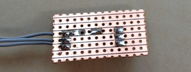
To start our build we need a small section of strip board and a set of three wires for power, ground and IR Out.
These can be soldered to the strip board so each leg of the IR Detector is connected through the copper strips of the strip board to one strand of the cable. In the picture I have used a section of ribbon cable, the cable should be long enough to suite your application, for example long enough to mount the detector on the steering column support of your Kart and allow you to attach the main unit to the steering wheel - don't make the cable longer than necessary it will only get in the way and may pick up interference.
Notice that the IR Detector is facing away from the connecting wires and that there is room for some additional components between the detector and the connecting wires, this is to allow us to add an indicator ID.
Reverse Side View
Next we add a 10K current limiting resistor between the output of the IR Detector and the wire we will be connecting to our Arduino interrupt pin.
For this resistor to have any effect we need to cut the copper track underneath the resistor so that the current has to pass through the resistor, a 3mm or 3.5mm drill bit will do this nicely.
Reverse view showing the cut in the copper track beneath the 10K resistor
Next we need to add the current limiting resistor for our indicator LED, I am using 560, but anything from 500 to 800 Ohms should be fine. This resistor connects from the row with the VCC Pin of the detector to the row below the Vout pin. From here we can also add two short lengths of connecting wire for our indicator LED, on wire should come from the VOut track and another from the track below VOut where we have just added the resistor.
This is to allow use to add an indicator LED which will light whenever the unit receives an IR Signal, this is useful as it will let you know if there is environmental interference such as reflected sunlight or fluorescent lighting.
At this point you should have the following circuit -
You can now add an indicator LED of whatever colour will be most visible in your application. To connect the LED, the long leg should be connected to the length of wire which is soldered to the same row as the 560 Ohm resistor, the shorted leg should be connected to same the same row as the Vout pin of the IR Detector.
You can test this set up immediately by connecting 4 to 6 volts to the circuit, the positive voltage should be applied to the top row, the ground should be connected to the middle row. If you use a TV Remote or the Transponder from part 3 of the build along, you should see the LED Light, if not, try swapping the LED around incase it was soldered in reverse.
This is essentially the same circuit as shown in the Lady Ada tutorial -
Assuming that you have tested your detector correctly, we can now connect it to the Lap Timer.
To do this we need to connect the Vcc wire (top pin/wire in the picture assuming the detector is facing away from the connecting wires) to the 5V supply of the Arduino. Next we need to connect the center wire to the ground of the Arduino. Finally connect the bottom wire to digital pin 2 of your Arduino.
Congratulations, you have now finished the electronics however to be able to use the lap timer you need to build a small enclosure for the detector, without this sunlight and many type of indoor lighting will saturate your detector so that it is unable to detect signals. As I am based in Dubai where the sun is always fierce I have gone as far as spraying the inside of my enclosure with ultra matt camouflage paint. You can see the enclosures I have used in the following clips of the timer in action, not that the indicator LED is on the outside of the enclosure where we can see it - you knew that already right ?
Build Along Lap Timer in action complete with IR Detector as built in this post
I have recently added a few extensions to the project including a count down mode and support for external audio, you can see the new menu options and see them in action at the track in the following two clips -
New Menu Options
At the track with external audio enabled
The external audio option uses an LM386 based amplifier to drive
external speakers. You can use this IC to add big sound to any Arduino
project, here is a link to the circuit as used in the Lap Timer -
If you would like the latest code, contact me through the arduino forum for a zip file containing the full project.
Future Developments - I am considering adding support for three additional transponder types -
1) Magnetic - I am told that many Kart Tracks use a magnetic strip under the track which lapping Karts detect using a window sensor such as you would use for home security.
2) Commercial Beacons - The commercial beacons used at many auto racing tracks use a well know pattern of pulses, it would make sense to support this pattern allowing users to 'arrive and drive' without having to place your own transponder around the track.
3) User selected pulse length - Allow the user to choose a pulse length, this would allow two or three systems to be used alongside each other. All of the calculations needed to build your own unique transponder are linked in previous parts of build along.
The music generation algorithms take advantage of the repeating structure within binary numbers, an obvious development is a visualizer that would reveal some of the structure within the music.
This quick project uses the value of the algorithm output to drive the sound and visuals directly. The visualizer is simply a scrolling buffer of the 8 most recent output values.
While it would be possible to use FFT to visualize the music, in the case of algorithmic music it is more interesting to use the visualizer as a means to explore what is happening within the algorithm
rather than in the frequency spectrum.
The short video shows that even with no additional processing, the visuals are very different for each of the algorithms and reveal some of the structure within the music.
The first algorithm running from 0:11 to 0:38 produces a cascade effect reminiscent of the matrix - unfortunately this effect is subtle and needs development for the best effect. The second section of the video provides a more obvious demonstration of how the sound is being developed within the algorithm.
Some other ideas to explore in the future -
1) Bit rate - for each bit in the 8 bit output, increment a counter if it has changed from the last sample. Use the values for the 8-bits to drive the display
2) Divide by 2 - Use the current output for row 0, update row 1 every second output, row 2 every fourth output, row 3 every 8 etc upto 128
For now, here is a scrolling buffer of the 8 most recent output values (and a little reaction from the family)
UK Based electronics supplier RS-Online have added a new Arduino section to the home page of thier site.
Clicking on the links will take you to this section with an overview of the new starter kit, some video demonstrations and datasheets.
These are the 15 projects included in the new official Arduino starter kit -
01 GET TO KNOW YOUR OWN TOOL an introduction to the concepts you'll need to use this kit
02 SPACESHIP INTERFACE design to control panel for your starship
03 LOVE-O-METER measure how hot-blooded you are
04 COLOR MIXING LAMP produce any color with a lamp that uses light as an input
05 MOOD CUE clue people in to how you're doing
06 LIGHT THERIM create a musical instrument you play by waving your hands
07 KEYBOARD INSTRUMENT play music and make some noise with this keyboard
08 DIGITAL HOURGLASS a light-up hourglass that can stop you from working too much
09 MOTORIZED PINWHEEL a color wheel that will have your head spinning
10 ZOETROPE create a mechanical animation you can play forward or reverse
11 CRYSTAL BALL a mystical tour to answer all your tough question
12 KNOCK LOCK tap out the secret code to open the door
13 TOUCHY-FEEL LAMP a lamp that responds to your touch
14 TWEAK THE ARDUINO LOGO control your personal computer from your Arduino
15 HACKING BUTTONS create a master control for all your devices!
More information including the video tutorials can be found here -
While the site does not mention the upcoming Arduino Due, there is a 'stay tuned for Arduino' email notification which you can subscribe to in the link above. If RS have any marketting sense I am sure they will use this mailing list to announce the availability of Due or pre orders.
The RC Arduino site has featured a number of Audio projects recently, and while they all produce very different sounds they all use the same basic technique to generate their sound.
With this in mind an obvious development of these projects would be a modular synthesizer which allows the user to easily combine the techniques used by individual projects to produce new instruments.
Modular Synthesizer
A modular synthesizer is traditionally a large analogue device often including a mix and match of vintage components. Early models were often enormous DIY machines that could easily take up a whole wall of a room.
Current models are still large in comparison to digital synthesizers this is partly due to the physical user interface which is also what gives these machines their character.
A typical modular synthesizer user interface - Analog inputs to control the module oscillators and a patchwork of wires to direct the signals between different modules.
Original photo by Nina Richards
Arduino as a Digital Modular Synth ?
While the Arduino is a digital device, the Auduino and Illutron B projects both demonstrate the appeal of using analog inputs to control an Arduino based digital synthesizer.
Auduino
Illutron B
Auduino Features -
A grain synthesizer which uses two
triangle waveforms with independently controlled frequency and decay to
create a more complex waveform. A fifth control is then used to set the
pitch by controlling the repetition rate of the complex waveform.
The
tone of the waveform can be dramatically altered by adjusting the
frequencies of the two component waveforms.
Illutron B Features -
A wavetable synthesizer which uses
pre calculated waveforms stored within the program memory. These
waveforms are played back at different speeds to produce sound at the
required pitch. To further increase the musical quality of the
waveforms, they are combined with an envelope, this describes how the
sound developes over time and can provide an approximation of many
musical instruments.
More information and examples of both of these projects can be found here -
The goal of this series of posts is to extend these ideas by -
1) Building a set of software components that will provide digital versions of the most common modules found in a modular synthesizer.
2) Building a simple, low cost simulated patch panel to
direct how the digital sound will be built and processed by the software
running on the Arduino.
Progress so far
Below are two examples of vastly different Arduino synthesisers built for this project with the same four oscillators connected in different ways - in effect this is a demonstration of the concept of an Arduino modular synthesiser.
As an initial experiment I wanted to build something that could be built from a few common components and that would be able to generate a reasonable range of new sounds.
The first result is the XLT2 - eXtemeley Limited Techno Toy.
An added bonus is that this synth and the Gated Grain Synth below are both directly compatible with the Auduino synth circuit, so if you have never built an Auduino before, now you have two more reasons to build one.
The XLT2 features two audio oscillators that are able to generate square, ramp or sine waveforms at audio frequencies.
These audio waveforms are then combined with individual low frequency oscillators ( LFOs ) which again generate square, ramp or sine waves but at much lower frequencies. These low frequency waveforms may not be audible on their own, but when we direct them to control the amplitude (volume) of an audio signal they can add a rythm, pulse or vibrato effect.
Each LFO also has an associated LED which reflects the LFO output both in frequency and profile - i.e. a squarewave will switch the LED hard on, then hard off whereas a sinewave will fade on and fade off reflecting the effect the LFO has on the audio signal.
A final control is provided to mix the two channels together according to a user selected ratio.
The Gated Grain Synthesizer
Once the XLT2 was up and running I wanted to try creating a similar sound to the Auduino using the same four oscillators as the XLT2, the grain synthesizer is the result.
This synth can produce a sound similar to the Auduino or even a passable violin if a sinewave is used as the output gate.
The main feature of the Gated Grain synth is that it sounds very different from the XLT2 but is built from the same four oscillators driving different aspects of the audio signal.
Proof of concept
The difference in sound between these two devices demonstrates the potential for an Arduino based synthesiser which allows the end user to configure the sound generation path using a simulated patch pannel. A follow up post will explore some of the options for implementing the patch pannel and how the relevant routing can be implemented at run time in software.
Getting Serious and moving to the Arduino Due
While this project has lots of potential for development the limited processing power of the 8-bit 16Mhz Arduino UNO will only get us so far.
The soon to be release Arduino Due platform however will allow the idea to be taken much further.
The Due has a built in analog to digital converter giving a true analog output rather than the UNOs PWM output, this together with higher resolution should provide far better sound quality.
The higher processing speeds of the Arduino Due will also allow for more oscillators and more importantly - complex relationships between the oscillators. It should also be possible to implement some software filters.
Perhaps the most exciting possibility is the high sampling rate offered by the Due, it may be possible to capture samples directly with the due and use them there and then as part of the synthesizer.
As the project stands, the user must select the waveforms at compile time however an obvious development would be to add a button for each oscillator allowing the user to cycle through the available waveforms. As my intention is to provide this function and others through a simulated patch panel, I will leave it to the user to add these buttons.
Note : The Audio output in the video is through a PC Speaker driven by the simple amplifier outlined in this post -