| Original By Viznut | Arduino Version |
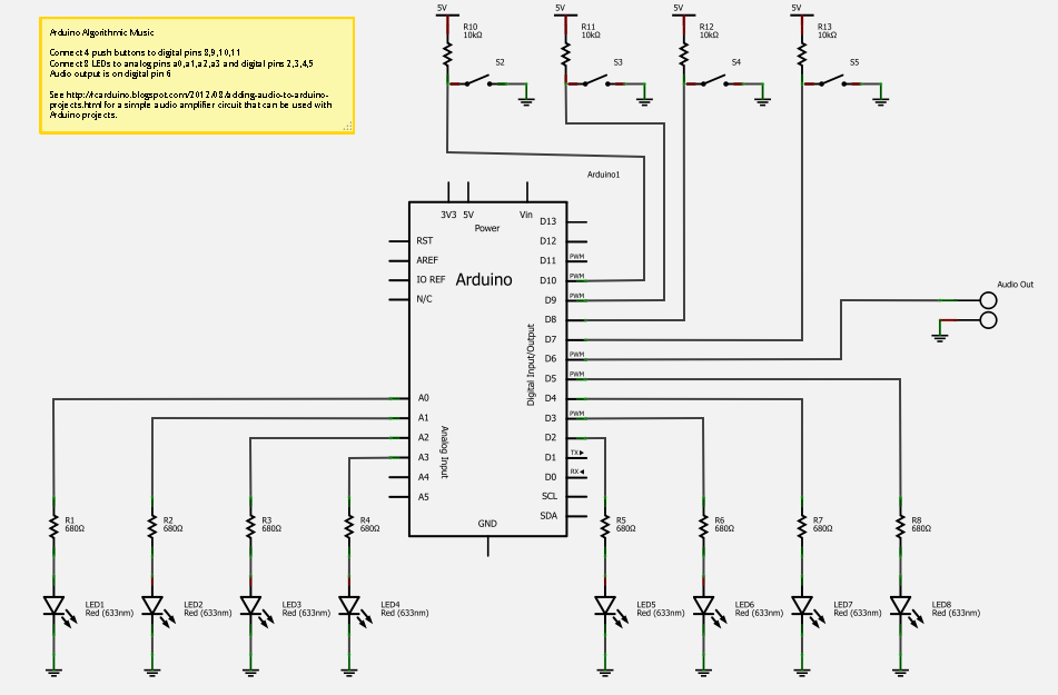
This is an interesting little project that can be built in minutes. It plays 13 different tunes all of which are generated from a single line of C code, the tunes are selected through four push buttons which have 16 possible combinations, including silence and two free slots for your own music.
The project also includes an 8 LED visualizer that is driven by the same line of code as the music.
About Algorithmic Music
The original tunes were produced by Viznut and by others in response to his original blog post here -
http://countercomplex.blogspot.com/2011/10/algorithmic-symphonies-from-one-line-of.html
The original Arduino port was completed by Arduino Forum user Stimmer and can be found in this post -
http://arduino.cc/forum/index.php/topic,74123.msg558213.html#msg558213
Arduino Forum user Zeni also has an interesting variation which allows the user to enter new algorithms at runtime, this can be seen in action in the forum topic above.
The RCArduino Version adds the ability to select the current algorithm and the 8 LED Visualiser.
The RCArduino Version code and schematic can be found below, if your interested in the theory behind the music or demoscene in general ( http://en.wikipedia.org/wiki/Demoscene ) you can pick up the trail from Viznuts original video linked at the start of this post.
An application in Grain Synthesis ?
One area that would be interesting to apply these techniques is grain synthesis. Grain synthesis is based on repeating a simple grain of sound while adding additional grains, envelopes, oscillators or filters to make the sound more interesting. These operations can be computationally expensive and do not always produce interesting sound. The techniques used to generate the algorithmic music from a simple counter demonstrated by Viznut could also be applied to generating more interesting synthesis grains.
The best known example of an Arduino Grain Synthesizer is the Auduino, its incredible to see that all of the sound generated by an auduino is the result of overlaying just two triangle waveforms. In one of the videos linked below you will see the triangle waveforms interacting together with the rich sound that results.
Examples of built Auduino Synths can be found at the end of this post -
http://rcarduino.blogspot.com/2012/08/adding-audio-to-arduino-projects.html
An interesting development of the grain synthesis would be to combine it with the realtime code upload work of Zeni, it should be possible to create grains that modulate and transform themselves to create a more interesting sound palette.
RCArduino Version - Based on original work of Viznut and original Arduino port of stimmer
// one-line algorithmic music
// see viznut's blog http://countercomplex.blogspot.com/2011/10/algorithmic-symphonies-from-one-line-of.html
// and http://www.youtube.com/watch?v=GtQdIYUtAHg&feature=related
// ported to arduino by stimmer
// Audio out on pin 10
// Further ported to Interrupt based music generation with 4 button selection of upto 16 algorithms (or 15 + silence on no buttons pressed)
// by Duane B aka RCArduino
//
// Buttons are digital 8,9,10,11, music output is on digital 6
//
// Also added a four LED Visualiser on digital pins 2,3,4,5
//
// Update - LED Visalizer is now 8 bit using digital pins 2,3,4,5 and analog pins 0,1,2,3
#define SAMPLE_MAX (65535.0)
#define SAMPLE_FREQUENCY (8000.0)
#define TIMER1_FREQUENCY 2000000
#define UPDATE_RATE 8000
// by keeping t global we can use it to drive the visualiser as well
long t;
// iterate the grains and LFO
SIGNAL (TIMER1_COMPA_vect)
{
OCR1A += (TIMER1_FREQUENCY/UPDATE_RATE);
t++;
switch(PINB&15)
{
default:
case 0:
OCR0A = 0;
break;
case 1:
OCR0A = ((-t&4095)*(255&t*(t&t>>13))>>12)+(127&t*(234&t>>8&t>>3)>>(3&t>>14)); // by tejeez
break;
case 2:
OCR0A = t*(t>>11&t>>8&123&t>>3); // by tejeez
break;
case 3:
OCR0A = t*((t>>9|t>>13)&25&t>>6); // by visy
break;
case 4:
OCR0A = (t*(t>>5|t>>8))>>(t>>16); // by tejeez
break;
case 5:
OCR0A = ((t*(t>>8|t>>9)&46&t>>8))^(t&t>>13|t>>6); // by xpansive
break;
case 6:
OCR0A = ((t&4096)?((t*(t^t%255)|(t>>4))>>1):(t>>3)|((t&8192)?t<<2:t)); // by skurk (raer's version)
break;
case 7:
OCR0A = (t>>7|t|t>>6)*10+4*(t&t>>13|t>>6); // by viznut, xpansive, varjohukka
break;
case 8:
OCR0A = t*5&(t>>7)|t*3&(t*4>>10); // by miiro
break;
case 9:
OCR0A = (t|(t>>9|t>>7))*t&(t>>11|t>>9); // by red
break;
case 10:
long v;
OCR0A = v=(v>>1)+(v>>4)+t*(((t>>16)|(t>>6))&(69&(t>>9))); // by pyryp
break;
case 11:
OCR0A = (t>>6|t|t>>(t>>16))*10+((t>>11)&7); //by viznut
break;
case 12:
OCR0A = (t*(4|7&t>>13)>>((~t>>11)&1)&128) + ((t)*(t>>11&t>>13)*((~t>>9)&3)&127); // by stimmer
break;
case 13:
// free to use
break;
case 14:
// free to use
break;
case 15:
// free to use
break;
// any more and we need another bit from PORTB
}
}
void setup()
{
TCCR1A=0x0; // set the timer prescaler to 8 = 16/8 = 2MHz
TCCR1B=0x02; // set the timer prescaler to 8 = 16/8 = 2MHz
TIMSK1 |= (1<<OCIE1A); // Enable output compare match interrupt on OCR1A
//TCCR0A=0B10110011; //-8 bit audio PWM
TCCR0A=0B10000011; //-8 bit audio PWM
//TCCR0A=0x83; // Set timer waveform generation mode to FAST PWM, clear OC0A On match, set at bottom - OC0A = digital pin 6.
TCCR0B=0x01; // Set to clock frequency, no prescaler
OCR0A=127; // set in the middle - do we need this ? probably not.
DDRD|=1<<6; // Set digital pin 6 to output - channels 2 and 3
DDRB &= (~15); // set digital pins 8,9,10,11 as inputs
DDRD |= ((1<<2) | (1<<3) | (1<<4) | (1<<5)); // set digital pins 2,3,4,5 as outputs for the visualiser
DDRC &= (15);
}
void loop()
{
unsigned char output = OCR0A;
// clear visualiser bits on portD
PORTD &= 0B000011;
// set the portd part of the visualiser using the top 4bits of output
PORTD |= ((output>>4)<<2);
// set the portc part of the visualiser using the bottom 4 bits of output
PORTC &= 0B110000;
PORTC |= (output & B1111);
}
For a simple amplifier circuit to use with Arduino projects see here -
http://rcarduino.blogspot.com/2012/08/adding-audio-to-arduino-projects.html
I am currently working on an Arduino based modular synthesizer with a very different sound, stay tuned
Duane B.
Totally creazy!! Love it! Is there any way to add some kind of midi or pulse sync??
ReplyDeleteThannk you for being you
ReplyDelete